A

B

C

D

Text Solution
Verified by Experts
The correct Answer is:


Topper's Solved these Questions
Similar Questions
Explore conceptually related problems
NARAYNA-SEMICONDUCTOR ELECTRONICS-EXERCISE-4
- The electrical conductivity of a semiconductor increases when electrom...
Text Solution
|
- In a full wave rectifier circuit operating from 50 Hz mains frequency ...
Text Solution
|
- In a common-base amplifier, the phase difference between the input sig...
Text Solution
|
- A solid which is not transperent to visible light and whose conductivi...
Text Solution
|
- If the ratio of the concentration of electron to that of holes in a se...
Text Solution
|
- In a common base mode of transistor, collector current is 5.488 mA for...
Text Solution
|
- If the lattice constant of this semiconductor s decreases, then which ...
Text Solution
|
- In the following, which one of the diodes is reverse biased ?
Text Solution
|
- The circuit has two oppositely connected ideal diodes in parallel. Wha...
Text Solution
|
- Carbon, silicon and germanium have four valence electrons each. The mo...
Text Solution
|
- If a pn junction dide, a square input signal of 10 V is applied as sho...
Text Solution
|
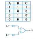
- In the circuit below, A and B represent two inputs and C represents th...
Text Solution
|
- A p-n junction (D) shown in the figure can act as a rectifier. An alte...
Text Solution
|
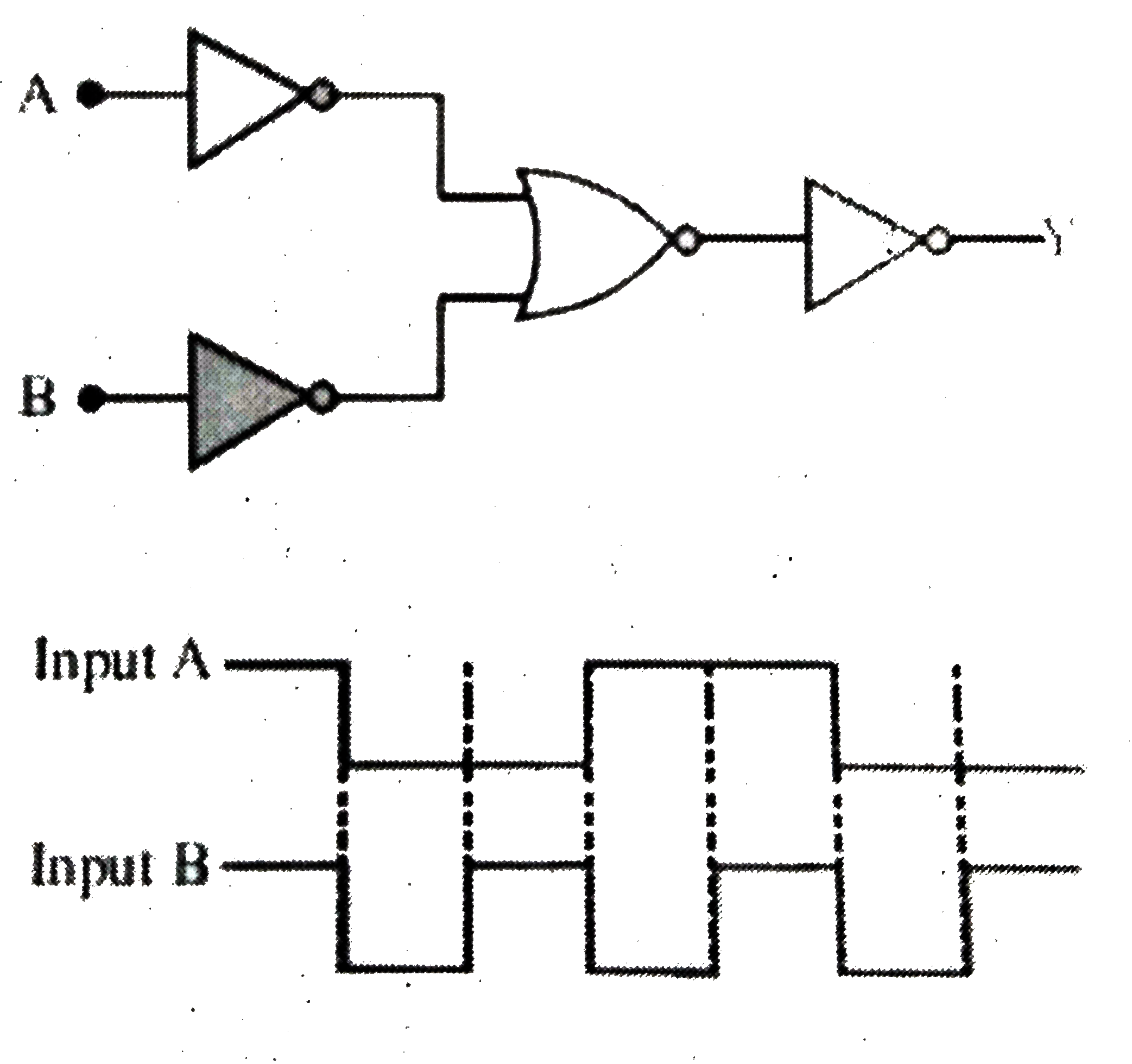
- The logic circuit shown has the input waveforms 'A' and 'B' as shown. ...
Text Solution
|
- The combination of gates shown below yields
Text Solution
|
- Truth table for system of four NAND gates as shown in figure is
Text Solution
|
- A diode detector is used to detect an amplitude modulated wave of 60% ...
Text Solution
|
- The I-V characteristic of an LED is.
Text Solution
|
- The currect voltage relation of diode is given by 1=(e^(1000 V//T)-1) ...
Text Solution
|
- The forward biased diode connection is
Text Solution
|