Home
Class 12
PHYSICS
In the circuit shown in figure potential...

In the circuit shown in figure potential difference between the points `A` and `B` in the steady state is

A

25

B

75

C

100

D

none of the above

Text Solution

Verified by Experts

The correct Answer is:
1

The circuit can be redrawn after reducing the equipotential points and dropping resistances as they do not produce a potential drop in the steady state.

Potential difference between A and C is 100 volt. This is divided in the inverse ratio of equivalent capacitances. ltb rgt `therefore V_(AB)=(100V)/((6+2)muF)xx2muF=25V`
`therefore V_(BC)=(100V)/((6+2)muFxx6muF)=75V`
Promotional Banner

Topper's Solved these Questions

  • CIRCULAR MOTION

    ALLEN|Exercise EXERCISE (J-A)|6 Videos
  • GEOMETRICAL OPTICS

    ALLEN|Exercise subjective|14 Videos

Similar Questions

Explore conceptually related problems

In the circuit shown in figure potential difference between A and B is

In the circuit shown in figure-3.331, the potential difference between points A and Bis :

The potential difference between the points A and B in the given circuit is

The potential difference between the points A and B in the following circuit in steady state will be .

In the circuit shown in figure -3.113 Find potential difference between the point A and B and the currents though each branch.

The potential difference between the point A and B in figure will be

In the circuit shown, the potential difference between A and B is:

In the given circuit, the potential difference between the points A and B is

In circuit shown in figure calculate the potential difference between the points A and B and between the points B and C in the steady state.

ALLEN-CURRENT ELECTRICITY-All Questions
  1. A galvanometer of resistance 50Omega is connected to a b attery of 3V ...

    Text Solution

    |

  2. A current of 3 A flows through the 2 Omega resistor as shown in the ci...

    Text Solution

    |

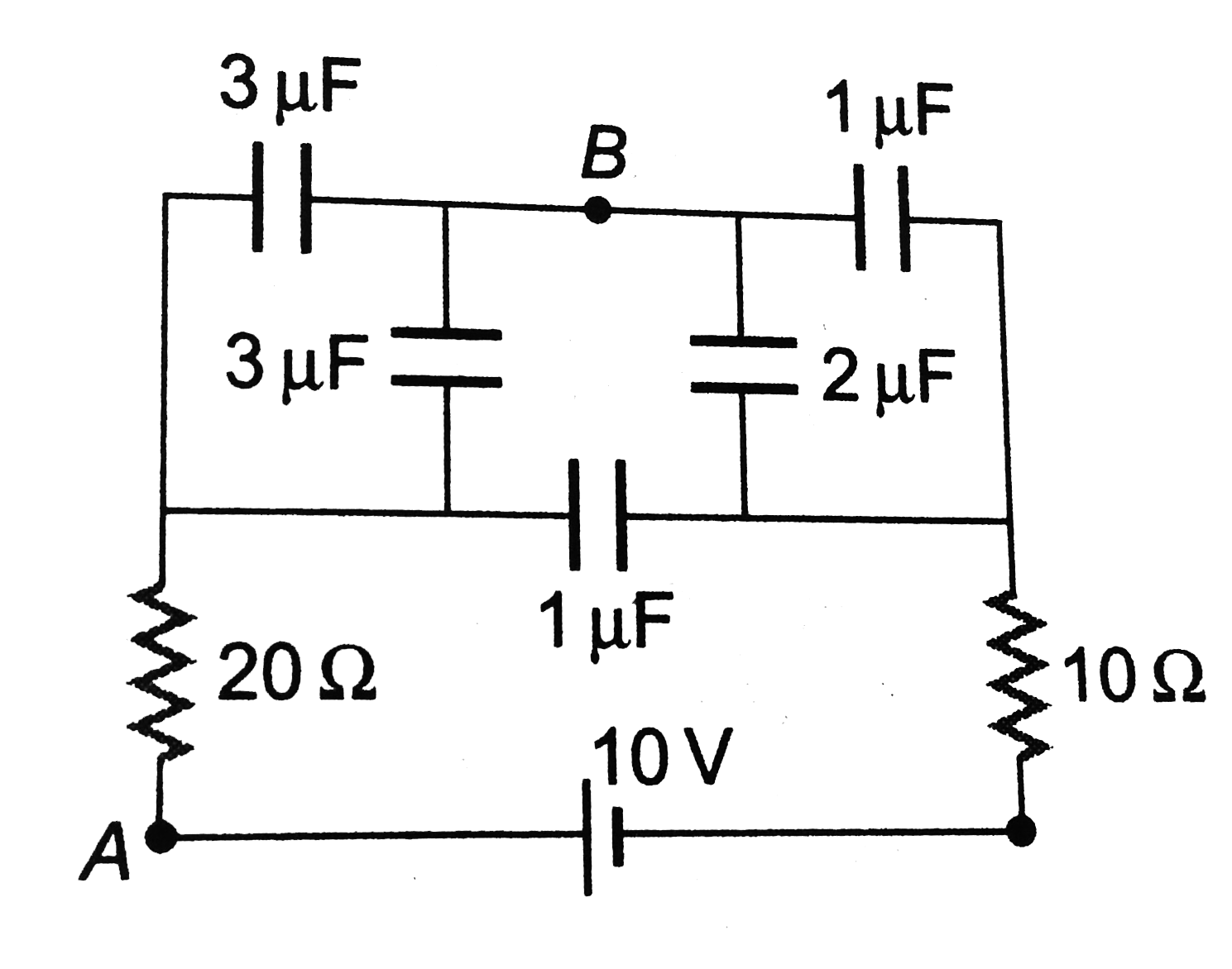
  3. In the circuit shown in figure potential difference between the points...

    Text Solution

    |

  4. In which of the following the carriers of electric current are electro...

    Text Solution

    |

  5. To the potentiometer wire of L and 10Omega resistance, a battery of em...

    Text Solution

    |

  6. A wire of resistance 12 Omega m^(-1) is bent to from a complete circle...

    Text Solution

    |

  7. See the electrical circuit shown in this figure. Which of the followin...

    Text Solution

    |

  8. A galvanometer having a coil resistance of 60 Omega shows full scale...

    Text Solution

    |

  9. A student measures the terminal potential difference (V) of a cell (of...

    Text Solution

    |

  10. If an electron revolves in the circular path of radius 0.5A^(@) at a f...

    Text Solution

    |

  11. The external diameter of a 314 m long copper tube is 1.2 cm and the i...

    Text Solution

    |

  12. In the shown arrangement of the experiment of the meter bridge if AC c...

    Text Solution

    |

  13. A potentiometer circuit is setup as shown. The potential gradient acro...

    Text Solution

    |

  14. A galvanometer has a coil of resistance 100 Omega and gives a full-sc...

    Text Solution

    |

  15. Consider the following two statements: (A)Kirchhoff's junction law f...

    Text Solution

    |

  16. For a the current loops shown in the figu re, kirchhoff's loop rule f...

    Text Solution

    |

  17. In a potentiometer arrangment, a cell of emf 1.25 V gives a balance po...

    Text Solution

    |

  18. A current of 2 A flows through a 2 Omega resistor when connected acros...

    Text Solution

    |

  19. If power dissipated in the 9 Omega resistor in the resistor shown is 3...

    Text Solution

    |

  20. In the circuit shown in the figure, if potentail at point A is taken t...

    Text Solution

    |