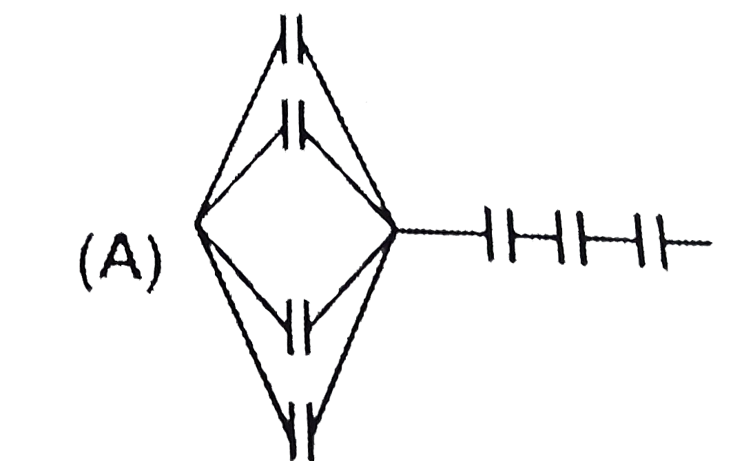
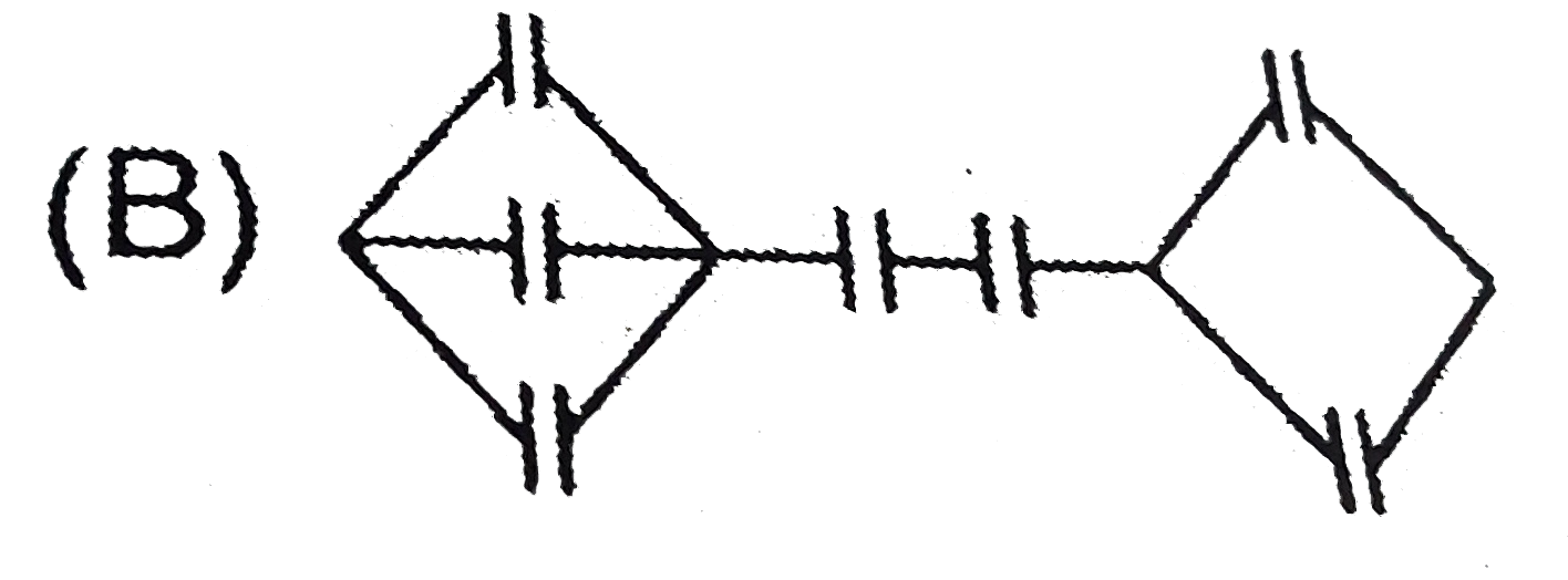
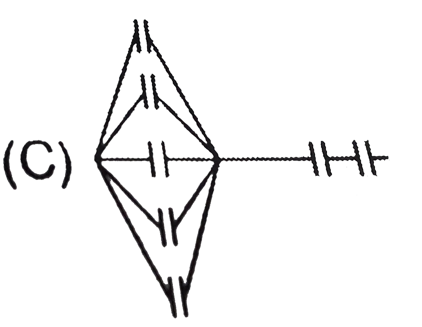
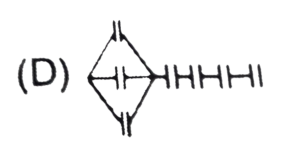
Home
Class 12
PHYSICS
Seven capacitors each of capacitance 2mu...

Seven capacitors each of capacitance `2muF` are to be connected in a configuration to obtain an effective capacitance of `(10/11)muF`. Which of the combination (s) shown in figure will achieve the desired result?

A

B

C

D

Text Solution

Verified by Experts

The correct Answer is:
C
Promotional Banner

Topper's Solved these Questions

  • CAPACITANCE

    RESONANCE|Exercise Exercise - 2|74 Videos
  • CAPACITANCE

    RESONANCE|Exercise Exercise - 3|26 Videos
  • CAPACITANCE

    RESONANCE|Exercise Miscellaneous Solved Example|3 Videos
  • ATOMIC PHYSICS

    RESONANCE|Exercise Advanved level problems|17 Videos
  • COMMUNICATION SYSTEMS

    RESONANCE|Exercise Exercise 3|13 Videos

Similar Questions

Explore conceptually related problems

Seven capacitors, each a of a cpacitance 2muF , are to be connected in a configuration to obatin an effective capacitance of ((16)/(13))muF . Which of the combinations, shown in figure below, will achieve the desired value ?

Three capacitors each of capacity 4 muF are to be connected in such a way that the effective capacitance is 6 muF . This can be done by

Six capacitors each of capacitance of 2muF are connected as shown in the figure. The effective capacitance between A and B is:

Three capacitors of capacitance 3 muF are connected in a circuit. Then, their maximum and minimum capacitance will be

Three capacitors of capacitance 3 muF are connected in a circuit. Then their maximum and minimum capacitances will be

Eight capacitors , each of capacitance 2muF are conneted as shown in the figure . The effective capacitance between point A and B is

Five capacitors each of capacitance 20muF are joined as shown in the figure. The equivalent capacitance between A and C is

Some capacitors each of capacitance 30 muF are connected as shown in. Calculate the equivalent capacitance between terminals A and B .

RESONANCE-CAPACITANCE-Exercise - 1
  1. The charge on the condenser of capacitance 2mu F in the following circ...

    Text Solution

    |

  2. Two parallel plate condensers of capacity 20 mF and 30 mF are charged ...

    Text Solution

    |

  3. Seven capacitors each of capacitance 2muF are to be connected in a con...

    Text Solution

    |

  4. In the circuit shown below the switch is closed at t=0. For 0 lt t lt...

    Text Solution

    |

  5. A capacitor of capacitance C is charged to a potential difference V(0)...

    Text Solution

    |

  6. A 3 mega ohm resistor and an uncharged 1 mu F capacitor are connecte...

    Text Solution

    |

  7. A 3 mega ohm resistor and an uncharged 1 mu F capacitor are connecte...

    Text Solution

    |

  8. A 3 mega ohm resistor and an uncharged 1 mu F capacitor are connecte...

    Text Solution

    |

  9. A 3 mega ohm resistor and an uncharged 1 mu F capacitor are connecte...

    Text Solution

    |

  10. An uncharged capacitor of capacitance 8.0 mu F is connected to a batte...

    Text Solution

    |

  11. An uncharged capacitor of capacitance 8.0 mu F is connected to a batte...

    Text Solution

    |

  12. An uncharged capacitor of capacitance 100 mu F is connected to a bat...

    Text Solution

    |

  13. An uncharged capacitor of capacitance 100 mu F is connected to a bat...

    Text Solution

    |

  14. The charge on each of the capacitors 0.16 ms after the switch S is c...

    Text Solution

    |

  15. The plates of capacitor of capacitance 10 mu F, charged to 60 mu C, a...

    Text Solution

    |

  16. The plates of capacitor of capacitance 10 mu F, charged to 60 mu C, a...

    Text Solution

    |

  17. The plates of capacitor of capacitance 10 mu F, charged to 60 mu C, a...

    Text Solution

    |

  18. The switch S shown in figure is kept closed for a long time and then ...

    Text Solution

    |

  19. The distance between the plates fo a parallel plate capacitor is d. A...

    Text Solution

    |

  20. On placing a dielectric slab between the plates of an isolated charg...

    Text Solution

    |