Text Solution
Verified by Experts
The correct Answer is:


Topper's Solved these Questions
CURRENT ELECTRICITY
RESONANCE|Exercise Exercise-1 (Part-2)|49 VideosCURRENT ELECTRICITY
RESONANCE|Exercise Exercise-1 (Part-3)|2 VideosCURRENT ELECTRICITY
RESONANCE|Exercise Solued miscellaneous Prolblems|8 VideosCOMMUNICATION SYSTEMS
RESONANCE|Exercise Exercise 3|13 VideosDAILY PRACTICE PROBLEM
RESONANCE|Exercise DPP.No.71|1 Videos
Similar Questions
Explore conceptually related problems
RESONANCE-CURRENT ELECTRICITY-Exercise-1 (Part-1)
- In the given circuit determine (a) Equivalent resistance (Including...
Text Solution
|
- In given circuit determine (a) Equivalent resistance (Including int...
Text Solution
|
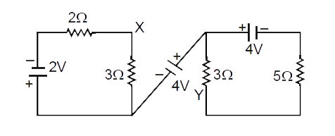
- Determine the potential difference between X and Y in the circuit show...
Text Solution
|
- Find the equivalent resistance of the circuit given in figure between ...
Text Solution
|
- An infinite ladder is constructed with 1(Omega)and 2(Omega)resistor as...
Text Solution
|
- As shown in figure a variable rheostat of 2kOmega is used to control t...
Text Solution
|
- ABCD is a square where each side is a uniform wire of resistance 1Omeg...
Text Solution
|
- Suppose you have three resistor of (20 omega),(50Omega)and (100 Omega)...
Text Solution
|
- Three bulbs,each having a resistance of 180(Omega)are connected in par...
Text Solution
|
- Consider the circuit shown in figure. Find the current through the 10O...
Text Solution
|
- Siix lead-acid type of secondary cells, each of emf 2.0 V and internal...
Text Solution
|
- In the figure each cell has an emf of 1.5 V and internal resistnce of ...
Text Solution
|
- In the circuit shown all live resistors have the same volue 200 oms an...
Text Solution
|
- Find the currents through the three resistors shown in figure
Text Solution
|
- Find the value of i(1)//I(2)in figure if (a)R=0.1(Omega) (b)R=1(Omega)...
Text Solution
|
- A galvanometer has a resistance of 30 Omega, and a current of 2 mA is ...
Text Solution
|
- A voltmeter of resistances 400(Omega)is used to measure the potential ...
Text Solution
|
- An electrical circuit is shown in figure. Calculate the potential diff...
Text Solution
|
- A battery of emf 1.4 V and internal resistance 2 Omega is connected to...
Text Solution
|
- A potentiometer wire AB having length L and resistance 12 r is joined ...
Text Solution
|