Text Solution
Verified by Experts


Topper's Solved these Questions
CURRENT ELECTRICITY
FIITJEE|Exercise SOLVED PROBLEMS (OBJECTIVE)|20 VideosCURRENT ELECTRICITY
FIITJEE|Exercise Exercise|9 VideosCURRENT ELECTRICITY
FIITJEE|Exercise Illustration|10 VideosCOLLISION
FIITJEE|Exercise (NUMERICAL BASED QUESTIONS)|4 VideosELASTICITY AND WAVES
FIITJEE|Exercise Assignment Problems (Objective) Level-II|15 Videos
Similar Questions
Explore conceptually related problems
FIITJEE-CURRENT ELECTRICITY-SOLVED PROBLEMS (SUBJECTIVE)
- A thin uniform wire AB of length 1 m, an unknown resistance X and a re...
Text Solution
|
- n' cells , each of emf 'e' and internal resistance 'r' are connected i...
Text Solution
|
- Eight identical resistors, each of resistance Y, are connected along e...
Text Solution
|
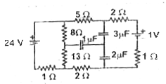
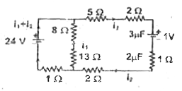
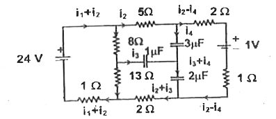
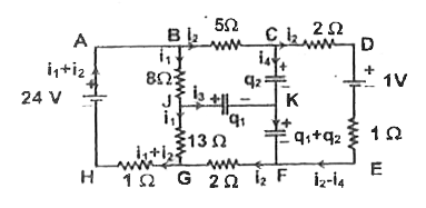
- Analyse the circuit shown in the figure in steady state
Text Solution
|
- Two cells having emf's of 10 V and 8 V, and internal resistance of 1Om...
Text Solution
|
- Shown in the figure is network of capacitors & resistors. The potentia...
Text Solution
|
- Consider a Wheatstone bridge with resistance and capacitance connected...
Text Solution
|
- The given RC circuit has two switches S(1) and S(2) The switch S(2) is...
Text Solution
|
- Find the current flowing through the branch AC in the steady state as ...
Text Solution
|
- In the circuit shown, r = 4 Omega, C = 2mu F (a) Find the current co...
Text Solution
|