A
B
C
D
Text Solution
Verified by Experts
The correct Answer is:


Topper's Solved these Questions
CURRENT ELECTRICITY
FIITJEE|Exercise Exercise|9 VideosCURRENT ELECTRICITY
FIITJEE|Exercise Comprehension Based Type-1|3 VideosCURRENT ELECTRICITY
FIITJEE|Exercise SOLVED PROBLEMS (SUBJECTIVE)|10 VideosCOLLISION
FIITJEE|Exercise (NUMERICAL BASED QUESTIONS)|4 VideosELASTICITY AND WAVES
FIITJEE|Exercise Assignment Problems (Objective) Level-II|15 Videos
Similar Questions
Explore conceptually related problems
FIITJEE-CURRENT ELECTRICITY-SOLVED PROBLEMS (OBJECTIVE)
- A cylindrical conductor has uniform cross-section. Resistivity of its ...
Text Solution
|
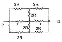
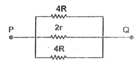
- The effective resistance between points P and Q of the electrical circ...
Text Solution
|
- if E denotes electric field in a uniform conductor and v(d) the corres...
Text Solution
|
- A source of constant potential difference is connected across a conduc...
Text Solution
|
- Current-voltage characteristics of two elements A and B are as shown b...
Text Solution
|
- In the given network, the batteries getting charged are
Text Solution
|
- When a galvanometer is shunted with a 4Omega resistance the deflection...
Text Solution
|
- An electric of 5A is passing through a circuit contaning three arrenge...
Text Solution
|
- When the key E is pressed at time t = 0, which of the following statem...
Text Solution
|
- Two electric bulbs rated P(1) and P(2) watt at V volt are connected in...
Text Solution
|
- The time constant T for the shown circuit containing resistance and ca...
Text Solution
|
- Is correct. In the circuit shown in the figure, the voltmeter reading ...
Text Solution
|
- The equivalent capacitance between A and B in the circuit shown is
Text Solution
|
- Two capacitors, having equal capacitance C, are having same charges q ...
Text Solution
|
- In the circuit shown, switch S is placed in position 1 till the capaci...
Text Solution
|
- If two bulbs of 25 W and 100 W rated at 200 volts are connected in ser...
Text Solution
|
- In the given circuit, with steady current, the potential drop across t...
Text Solution
|
- In the given circuit, R, 10Omega R(2) = 6Omega and E = 10V. Select the...
Text Solution
|
- In the circuit shown
Text Solution
|
- The electron in a hydrogen atom moves in a circular orbit of radius 5 ...
Text Solution
|