Text Solution
Verified by Experts


Topper's Solved these Questions
CURRENT ELECTRICITY
FIITJEE|Exercise ASSIGNMENT PROBLEMS (SUBJECTIVE)(Level-II//III)|14 VideosCURRENT ELECTRICITY
FIITJEE|Exercise ASSIGNMENT PROBLEMS (OBJECTIVE)(Level-1)|45 VideosCURRENT ELECTRICITY
FIITJEE|Exercise Matrix Match type|3 VideosCOLLISION
FIITJEE|Exercise (NUMERICAL BASED QUESTIONS)|4 VideosELASTICITY AND WAVES
FIITJEE|Exercise Assignment Problems (Objective) Level-II|15 Videos
Similar Questions
Explore conceptually related problems
FIITJEE-CURRENT ELECTRICITY-ASSIGNMENT PROBLEMS (SUBJECTIVE)(Level-1)
- A wire of resistance 15 Omega is bent to form a regular hexagon ABCDEF...
Text Solution
|
- Schematic of a rheostat is shown in the figure. Connect a battery to i...
Text Solution
|
- Consider an infinite ladder of network as shown in the adjacent figur...
Text Solution
|
- In the circuit shown in figure-3.391, V(1) and V(2) are two voltmeters...
Text Solution
|
- A galvanometer of resistance 95 Omega, shunted resistance of 5 Omega, ...
Text Solution
|
- Find the equivalent resistance between A & B in the given network
Text Solution
|
- The potential difference across 7Omega resistor is equal toand the cur...
Text Solution
|
- A capacitor of capacitance 10(mu)F is connected to a battery of emf 2V...
Text Solution
|
- Three 60 W , 120 V light bulbs are connected across a 120 V power line...
Text Solution
|
- A constant voltage V = 25 V is maintained between points A and B of th...
Text Solution
|
- Two resistors 400Omega and 800Omega are connected in series with a 6V ...
Text Solution
|
- Two cells, having emfs of 10 V and 8 V, respectively, are connected in...
Text Solution
|
- A galvanometer having 50 divisions provided with a variable shunt S is...
Text Solution
|
- A capacitor initially given a charge Q(o) is connected across a resist...
Text Solution
|
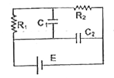
- In the circuit shown in figure, R(1) = 1Omega, R(2) = 2Omega, C(1) = 1...
Text Solution
|