


Similar Questions
Explore conceptually related problems
Recommended Questions
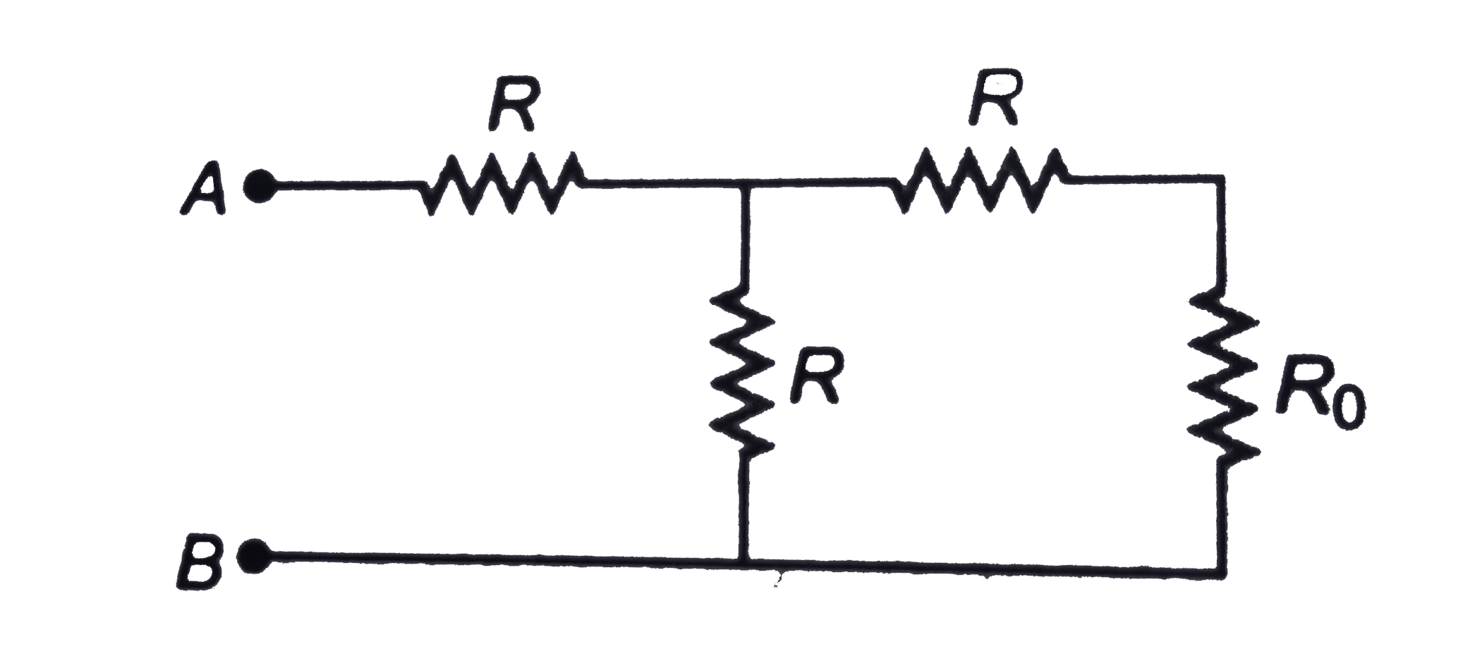
- In the circuit shown in figure the total resistance between points A a...
Text Solution
|
- In the circuit shown in figure the total resistance between points A a...
Text Solution
|
- Find the equivalent resistance of the circuits shown in figure between...
Text Solution
|
- For the network of resistance shown in the figure the equivalent resis...
Text Solution
|
- In the circuit shown, the value of each resistance is r , then equival...
Text Solution
|
- In the circuit shown in figure, each resistance is Net resistance betw...
Text Solution
|
- Each resistance of the circuit shown in figure is r. The equivalent re...
Text Solution
|
- The total electrical resistance between the points A and B of the circ...
Text Solution
|
- परिपथ में दिखाए गए प्रत्येक प्रतिरोध का मान r है तब परिपथ का बिंदु A ओ...
Text Solution
|