 .
. 


Similar Questions
Explore conceptually related problems
Recommended Questions
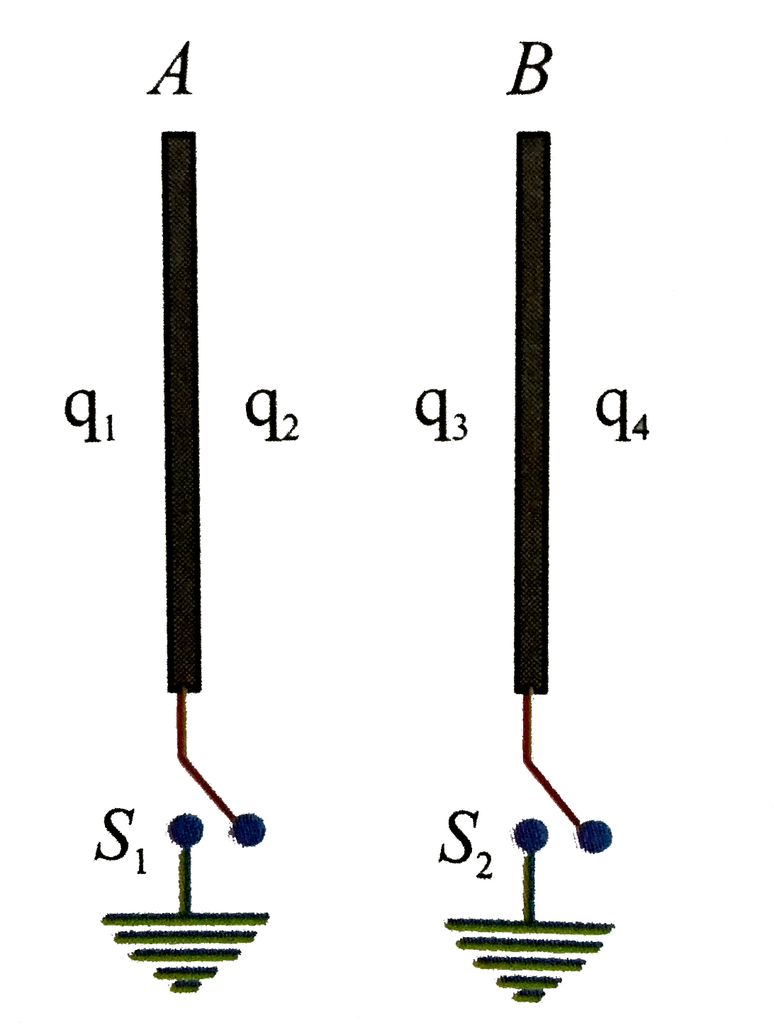
- In Figure the plate A has 100 muC charge, while the plate B has 60 mu ...
Text Solution
|
- In plate A has 100 muC charge, while plate B has 60 muC charge. a. Whe...
Text Solution
|
- Figure shows four plates each of plate area A and separated between pl...
Text Solution
|
- Three long conducting plates A, B and C having charges +q, -2q, and +q...
Text Solution
|
- In Figure the plate A has 100 muC charge, while the plate B has 60 mu ...
Text Solution
|
- In Figure the plate A has 100 muC charge, while the plate B has 60 mu ...
Text Solution
|
- In Figure the plate A has 100 muC charge, while the plate B has 60 mu ...
Text Solution
|
- The left plate of the capacitor shown in the figure above carries a ch...
Text Solution
|
- A parallel plate capacitor of capacitance 1 mu F has a charge of + 2 m...
Text Solution
|