


Similar Questions
Explore conceptually related problems
Recommended Questions
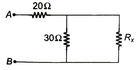
- A circuit shown in the figure has resistances 20 Omega and 30 Omega. A...
Text Solution
|
- A circuit shown in the figure has resistances 20 Omega and 30 Omega . ...
Text Solution
|
- At what value of the resistance in the circuit shown in the figure wil...
Text Solution
|
- In the given circuit if the internal resistance of the batteries are n...
Text Solution
|
- Find the equivalent resistance of the circuit between points A and B s...
Text Solution
|
- A circuit shown in Fig, has resistances R(1) = 20 Omega and R(2) = 30 ...
Text Solution
|
- In the circuit shown in figure-3.392, find the power supplied by 10 V ...
Text Solution
|
- Eight resistances each of resistance 5 Omega are connected in the circ...
Text Solution
|
- अग्र अभिनति की दशा में किसी जंक्शन डायोड का प्रतिरोध 30 Omega तथा...
Text Solution
|