


Similar Questions
Explore conceptually related problems
Recommended Questions
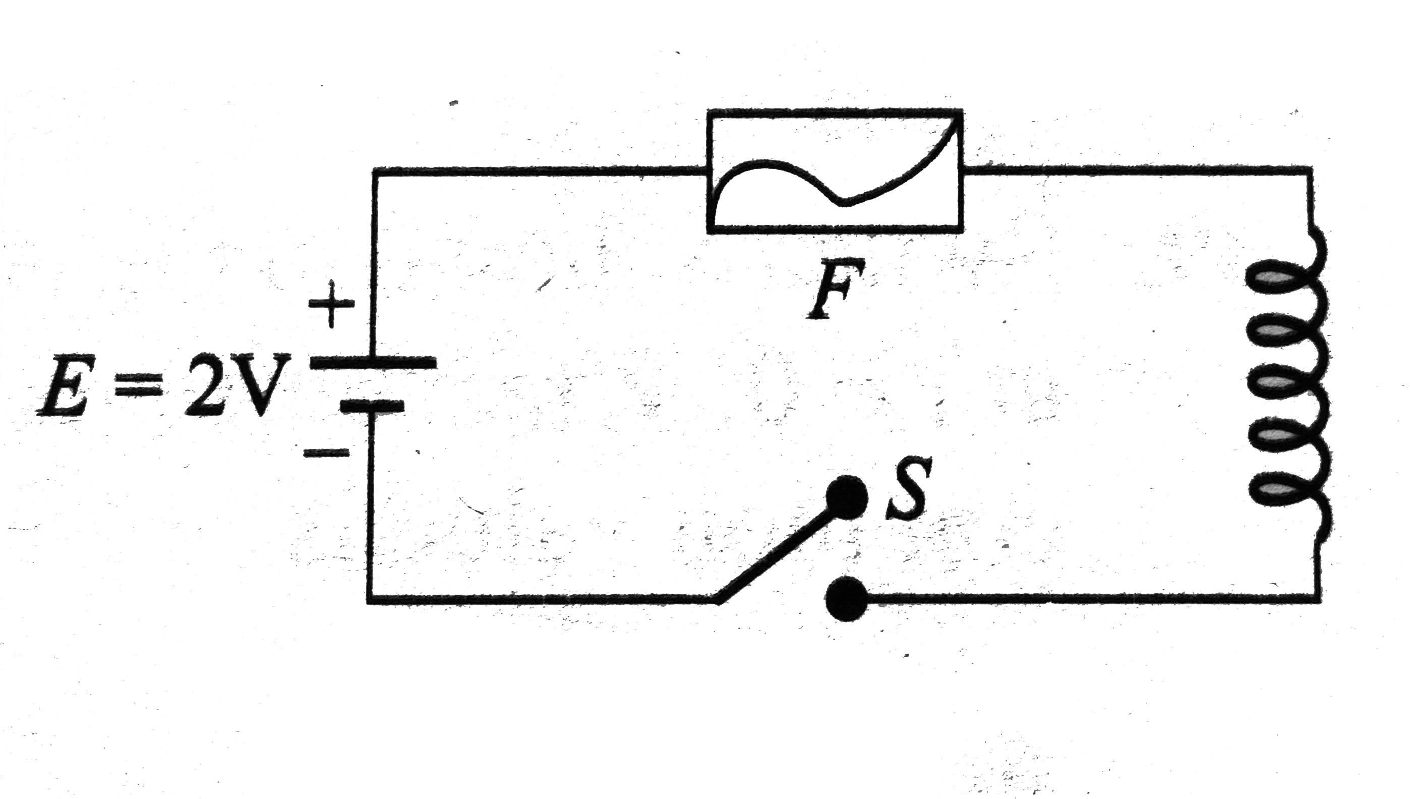
- In the circuit shows Fig the cell is ideal. The coil has an inductance...
Text Solution
|
- A coil of inductance 0.20 H is connected in series with a switch and a...
Text Solution
|
- In the circuit shows Fig the cell is ideal. The coil has an inductance...
Text Solution
|
- The cell in the circuit shows in Fig is ideal. The coil has an inducta...
Text Solution
|
- In the circuit shows in Fig the switch is closed at t = 0.
Text Solution
|
- In the circuit shown, the cell is deal. The coil has an inductance of ...
Text Solution
|
- Consider an ideal inductor (having no resistance) of inductance L whic...
Text Solution
|
- A fuse wire of circular cross-section has a radius of 1mm. This wire b...
Text Solution
|
- Figure-5.362 shows a circuit in which an inductor of 5H is a=connected...
Text Solution
|