


Similar Questions
Explore conceptually related problems
Recommended Questions
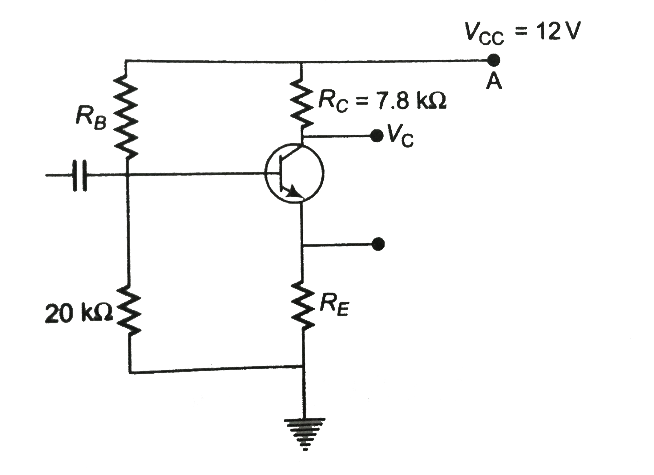
- For the transistor circuit shown in figure , evaluate VE , RB and RE. ...
Text Solution
|
- For the transistor circuit shown in figure , evaluate VE , RB and RE ....
Text Solution
|
- For the transistor circuit shown in figure , evaluate VE , RB and RE. ...
Text Solution
|
- In the accompanying circuit (Fig. 5.9) the value of beta is 100 . Find...
Text Solution
|
- In the circuit shown in figure, when the input voltage of the base res...
Text Solution
|
- एक उभयनिशष्ट उत्सर्जक ट्रांजिस्टर परिपथ के लिए V(CE) = - 20 V, Delta I...
Text Solution
|
- In the figure shown , RB=500kOmega, RC = 8 kOmega, V("BB")=10.6V and V...
Text Solution
|
- The output characteristics of a transistor is shown in the figure. Whe...
Text Solution
|
- In the circuit shown in the figure, the input voltage Vi = +5 V, V(BE)...
Text Solution
|