


Similar Questions
Explore conceptually related problems
Recommended Questions
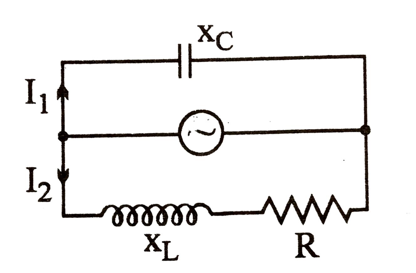
- In the shown AC circuit phase different between current I(1) and I(2) ...
Text Solution
|
- In the shown AC circuit phase different between current I(1) and I(2) ...
Text Solution
|
- In the given circuit assuming inductor and source to be ideal, the pha...
Text Solution
|
- In the circuit shown in figure ,find the ratio of currents i(1)//i(2).
Text Solution
|
- Find currents I(1),I(2) and I(3) and the energy stored in the capacito...
Text Solution
|
- In the network shown in figure. Find (i) the currents I(1),I(2) and I(...
Text Solution
|
- In the circuit shown, the currents i(1) and i(2) are
Text Solution
|
- In the circuit shown, the value of currents I(1), I(2) and I(3) are
Text Solution
|
- Find the phase difference between i(1) and i(2) in the two branches of...
Text Solution
|