


Similar Questions
Explore conceptually related problems
Recommended Questions
- In the circuit shown below (on the left) the resistance and the emf so...
Text Solution
|
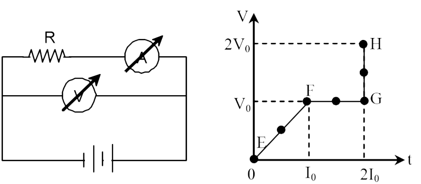
- A voltmeter and an ammeter are connected in series to an ideal cell of...
Text Solution
|
- In the circuit shown in figure neglecting source resistance the voltme...
Text Solution
|
- Two batteries, one of emf 18V and internal resistance 2Omega and the o...
Text Solution
|
- An ammeter and a voltmeter are connected in series to a battery of emf...
Text Solution
|
- In the circuit shown below (on the left) the resistance and the emf so...
Text Solution
|
- A battery of the emf 18 V and internal resistance of 1omega are connec...
Text Solution
|
- An ammeter and a voltmeter of resistance R are connected in series to ...
Text Solution
|
- R प्रतिरोध के एक वोल्टमीटर तथा नगण्य प्रतिरोध के अमीटर को एक नगण्य आं...
Text Solution
|