Home
Class 12
PHYSICS
The circuit diagram shows a logic combin...

The circuit diagram shows a logic combination with the states of outputs X , Y and Z given for inputs P , Q , R and S all at state 1 . When inputs P and R change to state 0 with inputs Q and S still at 1 , the states of outputs X , Y and Z changes to

A

1, 0 , 0

B

1 , 1 , 1

C

0 , 1 , 0

D

0,0,1

Text Solution

Verified by Experts

The correct Answer is:
C
Promotional Banner

Topper's Solved these Questions

  • SEMICONDUCTOR ELECTRONICS : MATERIALS , DEVICES AND SIMPLE CIRCUITS

    NEW JOYTHI PUBLICATION|Exercise PREVIOUS YEAR QUESTIONS|3 Videos
  • RAY OPTICS AND OPTICAL INSTRUMENTS

    NEW JOYTHI PUBLICATION|Exercise COMPETITIVE EXAM CORNER|26 Videos
  • WAVE OPTICS

    NEW JOYTHI PUBLICATION|Exercise COMPETITIVE EXAM CORNER|17 Videos

Similar Questions

Explore conceptually related problems

What is the output Y in the following circuit , When all the three inputs A,B, and C are first 0 and then 1?

For which one of the following input combinations , the given logic circuit gives the output Y = 1 ?

The inputs A , B and C to be given in order to get an output Y = 1 from the following circuit are

Given that P(3,1),Q(6. 5), and R(x , y) are three points such that the angle P Q R is a right angle and the area of R Q P is 7, find the number of such points Rdot

A greenhouse has an electronic system (block diagram is given below ) which automatically switches ON a heater if the air temperature in the greenhouse drops too low . A manual switch is included so that the automatic system can be switched off . (Hint , The temperature sensor gives a logic -I output when the air temperature is normal and logic 0 when it is too cold ) a. What is meant by 1 and 0 in digital circuit ? b. Name the logic gate X . Why is it used ? c. Name the logic gate Y. d. Construct a truth table of this electronic system by taking A and B as inputs and D as output

If from a point P , tangents P Qa n dP R are drawn to the ellipse (x^2)/2+y^2=1 so that the equation of Q R is x+3y=1, then find the coordinates of Pdot

Normals of parabola y^2=4 x at P and Q meet at R(x_2, 0) and tangents at P and Q mect-at T(x_1, 0) . If x_2=3 , then find the area of quadrilateral P T Q R .

Let P be a point on the ellipse x^2/a^2+y^2/b^2=1 , 0 < b < a and let the line parallel to y-axis passing through P meet the circle x^2 +y^2=a^2 at the point Q such that P and Q are on the same side of x-axis. For two positive real numbers r and s, find the locus of the point R on PQ such that PR : RQ = r : s and P varies over the ellipse.

Let C_1 and C_2 be parabolas x^2 = y - 1 and y^2 = x-1 respectively. Let P be any point on C_1 and Q be any point C_2 . Let P_1 and Q_1 be the reflection of P and Q, respectively w.r.t the line y = x then prove that P_1 lies on C_2 and Q_1 lies on C_1 and PQ >= [P P_1, Q Q_1] . Hence or otherwise , determine points P_0 and Q_0 on the parabolas C_1 and C_2 respectively such that P_0 Q_0 <= PQ for all pairs of points (P,Q) with P on C_1 and Q on C_2

If the x-coordinate of a point P on the join of Q(22,1)a n dR(5,1,-2)i s4, then find its z- coordinate.

NEW JOYTHI PUBLICATION-SEMICONDUCTOR ELECTRONICS : MATERIALS , DEVICES AND SIMPLE CIRCUITS -COMPETITIVE EXAM CORNER
  1. If the voltage between the terminals A and B is 17 V and Zener breakdo...

    Text Solution

    |

  2. GaAs (with a band gap = 1.5 eV) as a L.E.D can emit

    Text Solution

    |

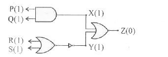
  3. The circuit diagram shows a logic combination with the states of outpu...

    Text Solution

    |

  4. In a common emitter transistor amplifier , the output resistance is 50...

    Text Solution

    |

  5. In the circuit given , the current through the zener diode is

    Text Solution

    |

  6. A transistor oscillator is (i) an amplifier with positive feedback (ii...

    Text Solution

    |

  7. A semiconductor with a band gap of 2.5 eV is used to fabricate a p-n p...

    Text Solution

    |

  8. In the circuit given A , B and C are inputs and Y is the output T...

    Text Solution

    |

  9. In the given circuits for ideal diode , the current through the batter...

    Text Solution

    |

  10. The logic gates giving output '1' for the inputs of '1' and '0' are

    Text Solution

    |

  11. Identify the mismatch of the following :

    Text Solution

    |

  12. If a PN junction diode of depletion layer width W and barrier height ...

    Text Solution

    |

  13. The heavily and lightly doped regions of a bipolar junction transistor...

    Text Solution

    |

  14. The device used for detecting optical signal is

    Text Solution

    |

  15. The logical operation carried out by the above circuit is

    Text Solution

    |

  16. In CE transistor amplifier , if the base current is increased by 20 mu...

    Text Solution

    |

  17. If an ideal junction diode is connected as shown , then the value of t...

    Text Solution

    |

  18. Identify the mismatched pair from the following

    Text Solution

    |

  19. In a common emitter configuration a transistor has beta = 50 and input...

    Text Solution

    |

  20. The wave forms A and B given below are given as input to a NAND gate ....

    Text Solution

    |