


Similar Questions
Explore conceptually related problems
Recommended Questions
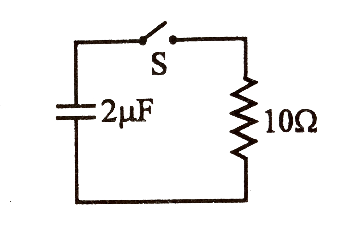
- In the R-C circuit shown in the figure the total enegry of 3.6 xx 10^(...
Text Solution
|
- Consider the circuit shown in figure.Find the current through the10(Om...
Text Solution
|
- In the R-C circuit shown in the figure the total enegry of 3.6 xx 10^(...
Text Solution
|
- In the circuit shown, the switch 'S' is closed at t =0 . Then capacito...
Text Solution
|
- The circuit consists of two resistors (of resistance R(1) = 20 Omega a...
Text Solution
|
- The circuit consists of two resistors (of resistance R(1) = 20 Omega a...
Text Solution
|
- Three capacitors (of capacitances C , 2C and 3C ) and three resistors ...
Text Solution
|
- A capacitor of capacitance 6 mu F and initial charge 1.60 muC is conne...
Text Solution
|
- The figure-3.375 shows two circuits with a charged capacitor that is t...
Text Solution
|