


Similar Questions
Explore conceptually related problems
Recommended Questions
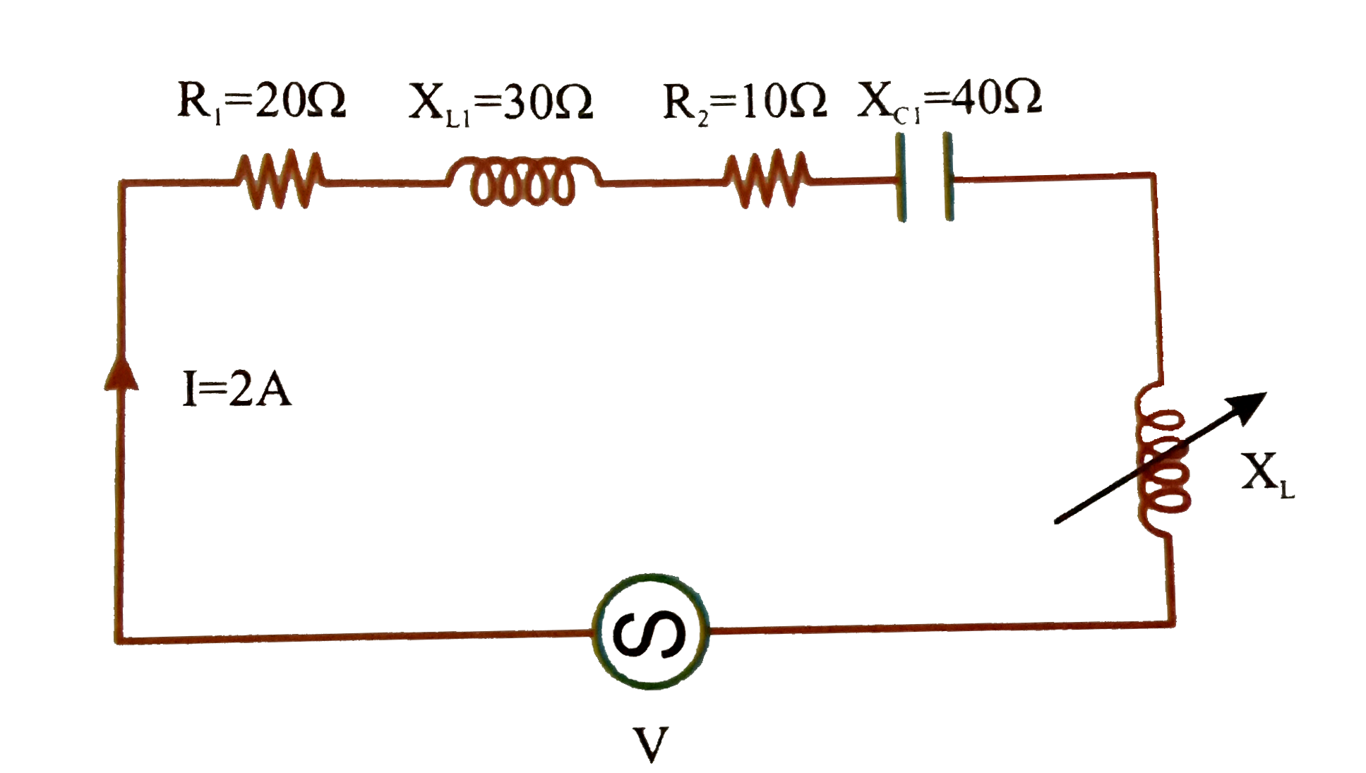
- As shown in figure value of inductive reactance X(L) will be (source v...
Text Solution
|
- If omega is angular frequency of a.c., then the reactance offered by i...
Text Solution
|
- As shown in figure value of inductive reactance X(L) will be (source v...
Text Solution
|
- An LCR series circuit is under resonance. If I(m) is current amplitude...
Text Solution
|
- एक परिपथ में प्रतिरोध R के सिरों के बीच विभवान्तर 40 वोल्ट, प्रेरकत्व ...
Text Solution
|
- The inductice reactance for a coil of inductance 5 mH when an alternat...
Text Solution
|
- Inductive reactance, X(L)=?
Text Solution
|
- An inductor of inductance L = 5 H is connected to an AC source having ...
Text Solution
|
- 1 kHz आवृत्ति की प्रत्यावर्ती धरा के लिए 100 mH के प्रेरकत्व ...
Text Solution
|