Home
Class 12
PHYSICS
In the circuits (A) and (b) switches S(1...

In the circuits (A) and (b) switches `S_(1)` and `S_(2)` are closed at t = 0 and are kept closed for a long time.The variation of current in the two circuits for `t ge 0` are roughly shown by figure (figures are schematic and not drawn to scale):

A

B

C

D

Text Solution

Verified by Experts

The correct Answer is:
C

For capaciotr circuit, `i = i_(0)e^(-t)/(RC)`
For inductor circuit, `i = i_(0)(1 - e^(-(Rt)/(L)))`
Hence graph (c) correctly depicts i versus t graph.
Promotional Banner

Topper's Solved these Questions

  • ALTERNATING CURRENT

    DISHA PUBLICATION|Exercise Exercise - 1 : CONCEPT BUILDER (Topic 3 : Transformers and LC Oscillations)|19 Videos
  • ATOMS

    DISHA PUBLICATION|Exercise EXERCISE-2: CONCEPT APPLICATOR|30 Videos

Similar Questions

Explore conceptually related problems

In the circuit shown in the figure, if switches S_(1) and S_(2) have been closed for a long time, then charge on the capacitor.

In the circuit shown, S_(2) is closed first and is kept closed for a long time. Now S_(1) is closed. Just after that instant the current through S_(1) is

In the circuit shown, switch S is closed at time t = 0 . Find the current through the inductor as a function of time t .

In the circuit as shown in figure the switch is closed at t = 0 . A long time after closing the switch

In circuit shown in figure-5.149 if switches S_(1) " and " S_(2) are closed at t=0, find the oscillation frequency of charge in this circuit. Neglect mutual induction between inductors.

In the circuit diagram shown in the figure the switches S_(1) and S_(2) are closed at time t=0 .After time t=(0.1)ln 2sec , switch S_(2) is opened.The current in the circuit at time t=(0.2)/n 2sec is equal to x/32amp .Find out value of x .

In the shown figures (1) and (2), capacitors are in steady state. Charging batteries are removed a switches S_(1) and S_(2) are closed at time t = 0 . The plot In I (I is the current in the resistor ) against time t the resitors R_(1) and R_(2) are shown in the figure. Choose the correct option (s) (1)

In the circuit shown, the switch is closed at t=0 , the currents I_1, I_2 and I_3 are

DISHA PUBLICATION-ALTERNATING CURRENT -Exercise -2 : Concept Applicator
  1. An inductive coil has resistance of 100 Omega. When an ac signal of fr...

    Text Solution

    |

  2. If a direct current of value a ampere is superimposed on an alternativ...

    Text Solution

    |

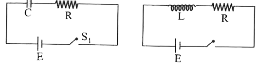
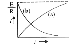
  3. In the circuits (A) and (b) switches S(1) and S(2) are closed at t = 0...

    Text Solution

    |

  4. Combination fo two identical capacitors, a resistor R and a dc voltage...

    Text Solution

    |

  5. In an alternating current circuit in which an inductance and capacitan...

    Text Solution

    |

  6. In a uniform magneitc field of induced B a wire in the form of a semic...

    Text Solution

    |

  7. A capacitor of 10 (mu)F and an inductor of 1 H are joined in series. A...

    Text Solution

    |

  8. A current source sends a current I=(i0) cos (omegat), When connected a...

    Text Solution

    |

  9. In a series LCR circuit R= 200(Omega) and the voltage and the frequenc...

    Text Solution

    |

  10. An ideal efficient transformer has a primary power input of 10 kW.The ...

    Text Solution

    |

  11. In the circuit shown in fig. R is a pure resistor, L is an inductor of...

    Text Solution

    |

  12. An inductive circuit contains a resistance of 10 ohms and an inductanc...

    Text Solution

    |

  13. In given circuit capacitorinitially uncharged.Now at t = 0 switch S is...

    Text Solution

    |

  14. In the circuit shown below, the key K is closed at t = 0. The current ...

    Text Solution

    |

  15. In a sereis L-C-R circuit, C = 10^(-11) Farad, L = 10^(-5) Henry and R...

    Text Solution

    |

  16. In an LCR circuit shown in the following figure, what will be the read...

    Text Solution

    |

  17. An AC voltage is applied to a resistance R and an inductance L in seri...

    Text Solution

    |

  18. An inductor of inductance L = 400 mH and resistors of resistance R(1) ...

    Text Solution

    |

  19. Consider the RLC circuit shown below connected to an AC source of cons...

    Text Solution

    |

  20. The circuit shown has been operating for a long time. The instant afte...

    Text Solution

    |