Home
Class 12
PHYSICS
In the circuit shown below, the key K is...

In the circuit shown below, the key K is closed at t = 0. The current through the battery is

A

`(VR_(1)R_(2))/(sqrt(R_(1)^(2) + R_(2)^(2))) at t = 0` and `(V)/(R_(2)) at t = infty`

B

`(V)/(R_(2))` at t - 0 and `(V(R_(1) + R_(2)))/(R_(1)R_(2))` at `t = infty`

C

`(V)/(R_(2)` at t = 0 and `(VR_(1)R_(2))/(sqrt(R_(1)^(2) + R_(2)^(2)))` at `t = infty`

D

`(V(R_(1) + R_(2)))/(R_(1)R_(2))` at t = 0 and `(V)/(R_(2))` at `t - infty`

Text Solution

Verified by Experts

The correct Answer is:
C

At t = 0, no current will flow through L and `R_(1)`
`therefore` Current through battery = `(V)/(R_(2))`
At `t = infty`
effective resistance, `R_(eff) = (R_(1)R_(2))/(R_(1) + R_(2))`
`therefore` Current through battery = `(V)/(R_(eff) = (V(R_(1)) + R_(2))/(R_(1)R_(2))`
Promotional Banner

Topper's Solved these Questions

  • ALTERNATING CURRENT

    DISHA PUBLICATION|Exercise Exercise - 1 : CONCEPT BUILDER (Topic 3 : Transformers and LC Oscillations)|19 Videos
  • ATOMS

    DISHA PUBLICATION|Exercise EXERCISE-2: CONCEPT APPLICATOR|30 Videos

Similar Questions

Explore conceptually related problems

In the circuit shown, the switch 'S' is closed at t = 0 . Then the current through the battery steady state reached is

In the circuit shown the key (K) is closed at t=0 , the current through the key at the instant t=10^-3 ln, 2 is

In the circuit shows in Fig. kay K is closed at t = 0 , the current through the key at the instant t = 10^(-3) In 2 s is

In the circuit shown below, the key is pressed at time t = 0. The correct statement is

In the circuit shown, switch S is closed at time t = 0 . Find the current through the inductor as a function of time t .

In th circuit the key (K) is closed at t=0 . Find the current in ampere through the key (K) at the instant t=10^(2)ln2 sec.

In the given circuit The current through the battery is

In the given circuit the current through the battery is

In the circuit shown in figure switch S is closed at time t=0 Current I from the battery at time t is given by

In the given circuit, the current through the battery is

DISHA PUBLICATION-ALTERNATING CURRENT -Exercise -2 : Concept Applicator
  1. A current source sends a current I=(i0) cos (omegat), When connected a...

    Text Solution

    |

  2. In a series LCR circuit R= 200(Omega) and the voltage and the frequenc...

    Text Solution

    |

  3. An ideal efficient transformer has a primary power input of 10 kW.The ...

    Text Solution

    |

  4. In the circuit shown in fig. R is a pure resistor, L is an inductor of...

    Text Solution

    |

  5. An inductive circuit contains a resistance of 10 ohms and an inductanc...

    Text Solution

    |

  6. In given circuit capacitorinitially uncharged.Now at t = 0 switch S is...

    Text Solution

    |

  7. In the circuit shown below, the key K is closed at t = 0. The current ...

    Text Solution

    |

  8. In a sereis L-C-R circuit, C = 10^(-11) Farad, L = 10^(-5) Henry and R...

    Text Solution

    |

  9. In an LCR circuit shown in the following figure, what will be the read...

    Text Solution

    |

  10. An AC voltage is applied to a resistance R and an inductance L in seri...

    Text Solution

    |

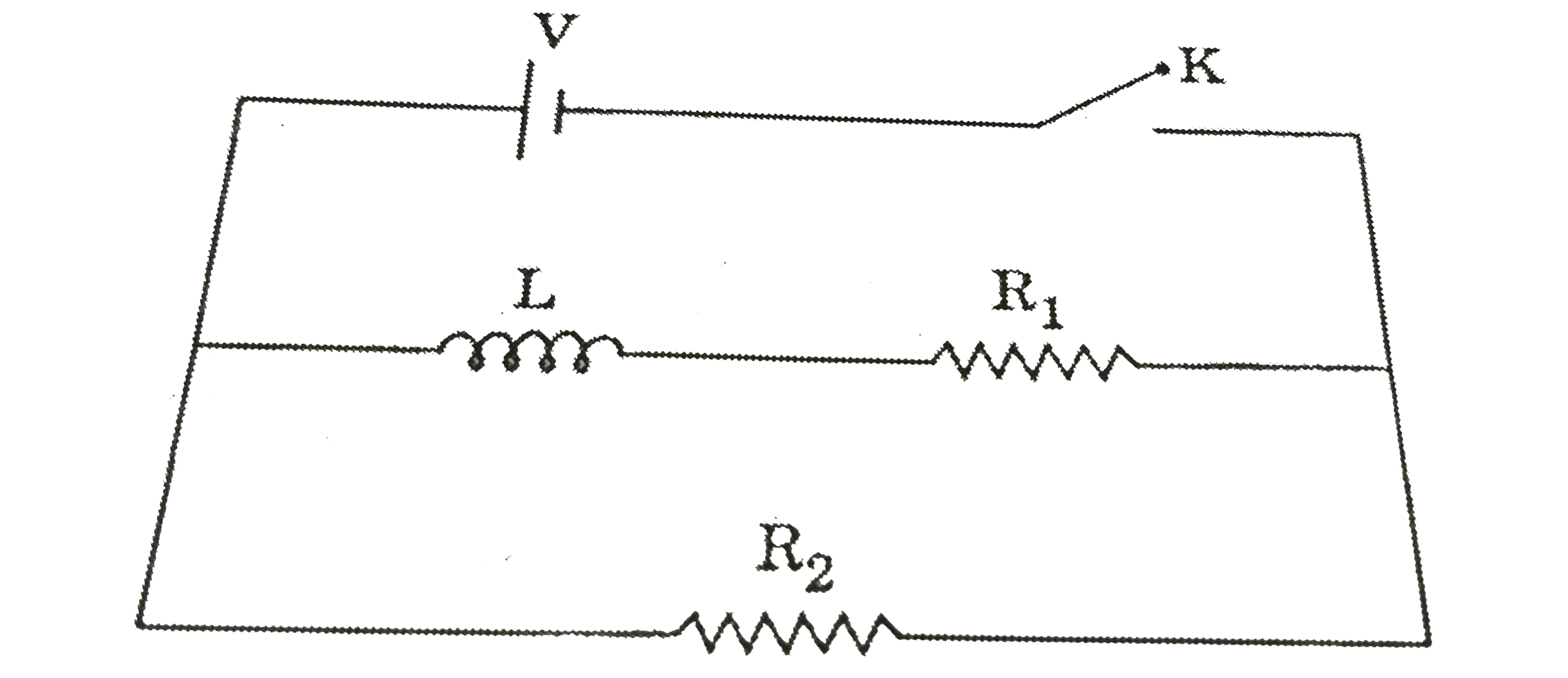
  11. An inductor of inductance L = 400 mH and resistors of resistance R(1) ...

    Text Solution

    |

  12. Consider the RLC circuit shown below connected to an AC source of cons...

    Text Solution

    |

  13. The circuit shown has been operating for a long time. The instant afte...

    Text Solution

    |

  14. Find the time constant (in mu s) for the given RC circuits in the give...

    Text Solution

    |

  15. In an LCR circuit as shown below both switches are open initially. Now...

    Text Solution

    |

  16. In an electrical circuit, R, I, C and AC voltage source are all connec...

    Text Solution

    |

  17. Find the current passing through battery immediately after key (K) is ...

    Text Solution

    |

  18. The two capacitors, shown in the circuit, are initially uncharged and ...

    Text Solution

    |

  19. In the given circuit, Fig., the reading of voltmeter V(1) and V(2) 300...

    Text Solution

    |

  20. Figure shows three oscillating LC circuit with identical inductors and...

    Text Solution

    |