


Similar Questions
Explore conceptually related problems
Recommended Questions
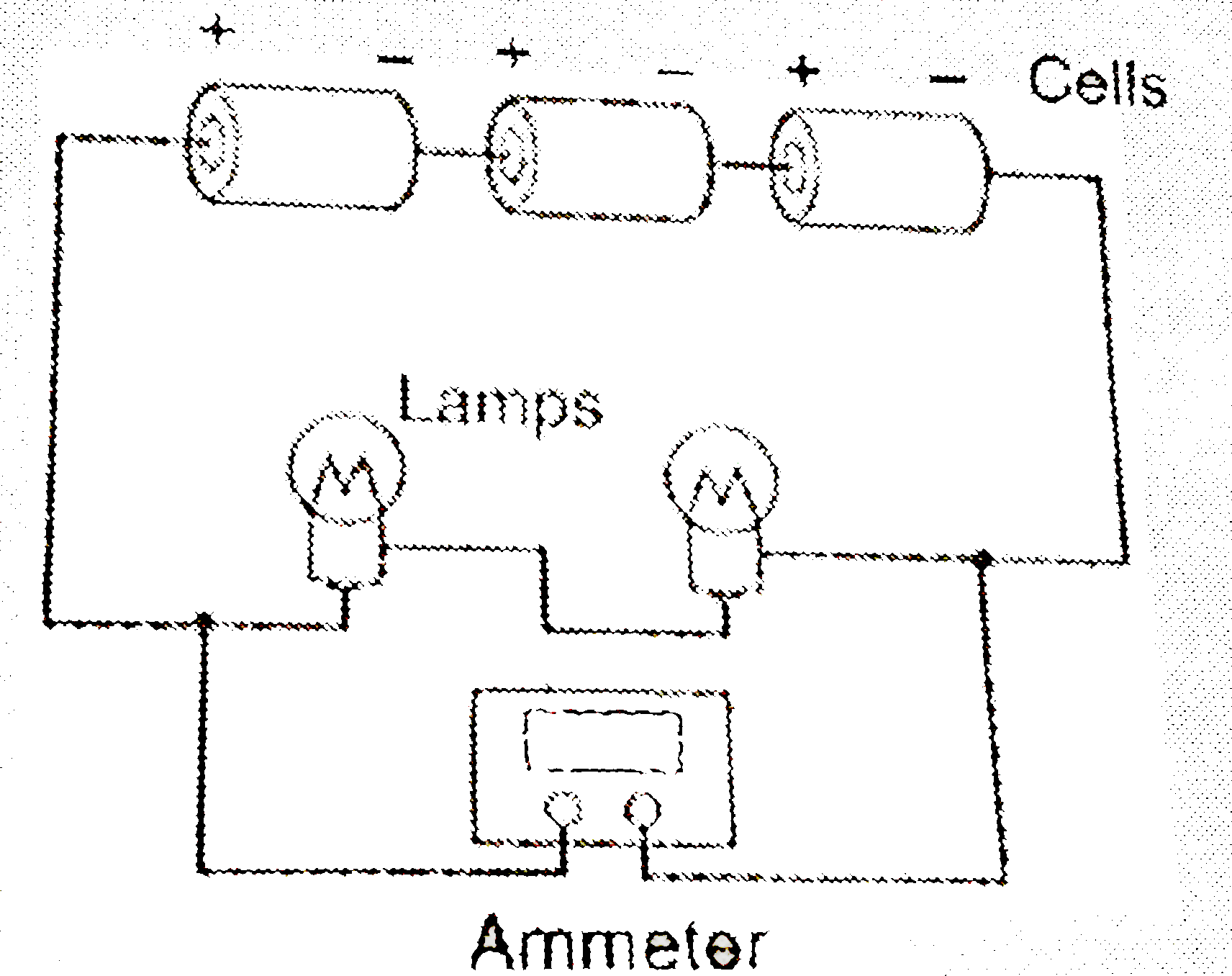
- A student made an electric circuit shown here to measure the current t...
Text Solution
|
- Circuit Diagram And Symbols For Circuit
Text Solution
|
- A student made an electric circuit shown here to measure the current t...
Text Solution
|
- Draw a circuit diagram to show how two 4V electric lamps can be lit br...
Text Solution
|
- (a) Which is the better way to connect lights and other electrical app...
Text Solution
|
- (a) Draw a circuit diagram showing two lamps, one cell and a switch co...
Text Solution
|
- A student stes up an electric circuit shown here for finding the equiv...
Text Solution
|
- Four student have made the following circuit diagrams for determining ...
Text Solution
|
- किसी प्रत्यावर्ती परिपथ में L ,C और R श्रेणीक्रम में जुड़े हैं ...
Text Solution
|