


Similar Questions
Explore conceptually related problems
Recommended Questions
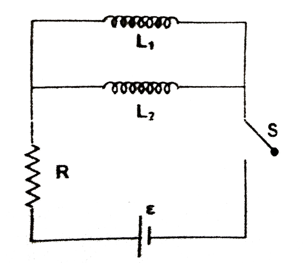
- In the circuit shown, switch's is closed at t=0. then the ratio (U(1))...
Text Solution
|
- In the circuit shown in fig, the energy stored in both capacitors is U...
Text Solution
|
- When a spring is compressed by a distance 'x' , the potential energy s...
Text Solution
|
- In the circuit shown in Fig. If both the lamps L(1) and L(2) are ident...
Text Solution
|
- In the circuit shown, switch's is closed at t=0. then the ratio (U(1))...
Text Solution
|
- In the circuit shown in the figure, if both the lamps L(1) and L(2) ar...
Text Solution
|
- Two inductors coils of self inductance 3H and 6H respectively are conn...
Text Solution
|
- Two inductor coils of self inductance 3H and 6H respectively are conne...
Text Solution
|
- A parallel plate capacitor having capacitance 0.5mu is taken. Plates a...
Text Solution
|