 .
.


Similar Questions
Explore conceptually related problems
Recommended Questions
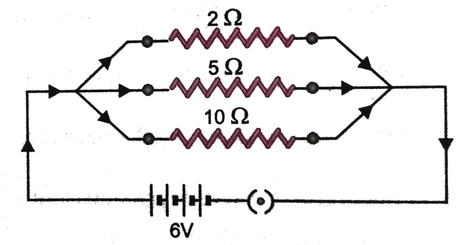
- In the circuit diagram given in (Fig. 3.57), calculate : (a) the cur...
Text Solution
|
- A 24 volt battery is connected to the arrangement of resistances shown...
Text Solution
|
- In the circuit diagram given in (Fig. 3.57), calculate : (a) the curre...
Text Solution
|
- In the circuit diagram given below, three resistors R(1),R(2), and R(3...
Text Solution
|
- (a) With the help of a diagram, derive the formula for the resultant r...
Text Solution
|
- In the circuit diagram given in Fig. 12.10, suppose the resistors R1, ...
Text Solution
|
- Calculate in the following power circuit - (a) Electric current flowin...
Text Solution
|
- In the given circuit , calculate the (i) effective resistance between...
Text Solution
|
- In the circuit diagram given below, three resistors R(1),R(2), and R(3...
Text Solution
|