


Similar Questions
Explore conceptually related problems
Recommended Questions
- In the circuit shown in figure-3.348 when the switch is closed, the in...
Text Solution
|
- Consider the circuit shown in figure.Find the current through the10(Om...
Text Solution
|
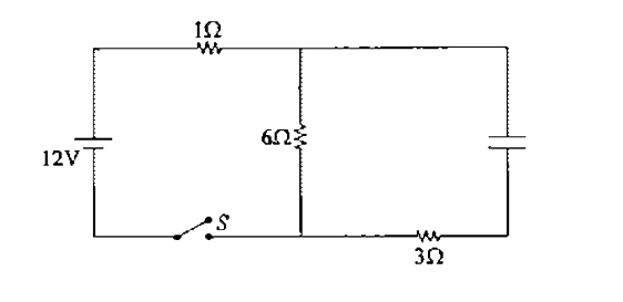
- When the switch is closed, the initial current through the 1Omega resi...
Text Solution
|
- In the circuit shown in figure, the capacitors are initially uncharged...
Text Solution
|
- When the switch S is closed at t=0, identify the correct statement jus...
Text Solution
|
- Refer to Fig. 7.49 . At t = 0 , the switch is closed . Just after clos...
Text Solution
|
- In the circuit shown, all the capacitors are initially uncharged. The ...
Text Solution
|
- In the circuit shown in figure-3.348 when the switch is closed, the in...
Text Solution
|
- In the circuit shown in figure-3.351 the capacitors are initially unch...
Text Solution
|