


Similar Questions
Explore conceptually related problems
Recommended Questions
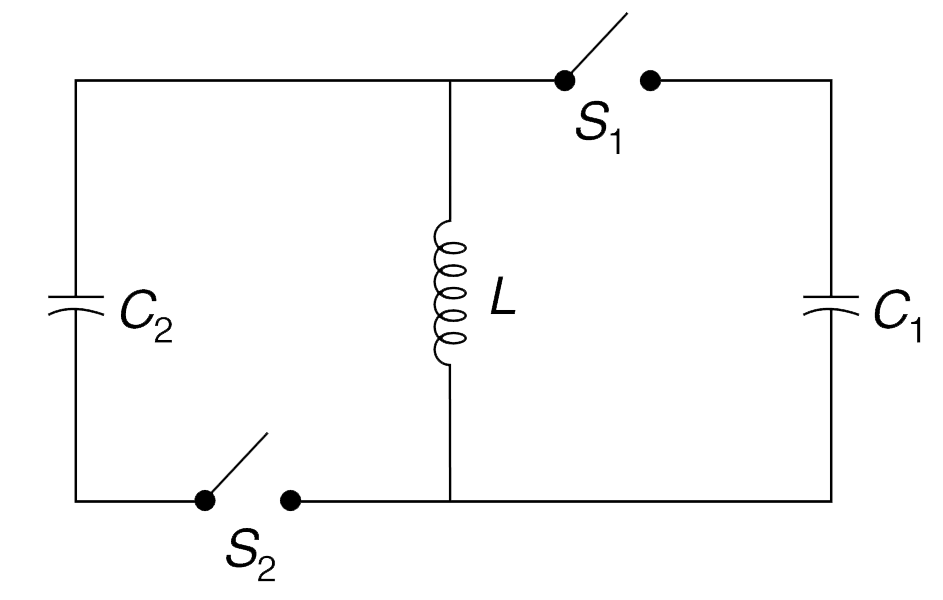
- The circuit shown in the figure is used to transfer energy from one ca...
Text Solution
|
- The circuit shows in Fig. is in the steady state with switch S(1) clos...
Text Solution
|
- In the circuit shows (Fig.) switches S(1) and S(3) have been closed fo...
Text Solution
|
- In the circuit in Fig. switch S(1) was closed for a long time . At tim...
Text Solution
|
- In the circuit in Fig. switch S(1) was closed for a long time . At tim...
Text Solution
|
- The circuit shown in the figure is used to transfer energy from one ca...
Text Solution
|
- In the circuit shown, the capacitor is initially charged with a 12V ba...
Text Solution
|
- Consider the circuit shown where C(1) = 6 mu F, C(2) = 3 mu F and V=20...
Text Solution
|
- As shown in diagram initial charge on capacitor is zreo . Now switch S...
Text Solution
|