Home
Class 12
PHYSICS
Capacitor 3 in Fig. 25-40a is a variable...

Capacitor 3 in Fig. 25-40a is a variable capacitor (its capacitance `C_3` can be varied) Figure 25-40b gives the electric potential `V_1` across capacitor 1 versus `C_3` The horizontal scale is set by `C_3s=12.0 mu F` Electric potential `V_1` approaches as asymptote of 8.0 V as `C_3 to infty` What are (a) the electric potential V across the battery , (b) `C_1` and (c) `C_2`?

Text Solution

Verified by Experts

`a) 8.0V b) 4.5 mu F c) 1.5 mu F`
Promotional Banner

Topper's Solved these Questions

  • CAPACITANCE

    RESNICK AND HALLIDAY|Exercise PRACTICE QUESTIONS (SINGLE CORRECT CHOICE TYPE)|23 Videos
  • CAPACITANCE

    RESNICK AND HALLIDAY|Exercise PRACTICE QUESTIONS (MORE THAN ONE CORRECT CHOICE TYPE)|12 Videos
  • CAPACITANCE

    RESNICK AND HALLIDAY|Exercise CHECKPOINTS|4 Videos
  • ALL ABOUT ATOMS

    RESNICK AND HALLIDAY|Exercise CHECKPOINT|1 Videos
  • CENTER OF MASS

    RESNICK AND HALLIDAY|Exercise Practice Questions (Integer )|4 Videos

Similar Questions

Explore conceptually related problems

Capacitor C_(3) in the circuit is variable capacitor (its capacitance can be varied). Graph is plotted between potential difference V_(1) (across capacitor C_(1) ) versus C_(3) . Electric potential V_(1) approaches on asymptote of 10 volts as C_(3) to infty The ratio of the capacitance C_(1)/C_(2) will be

Capacitor C_(3) in the circuit is variable capacitor (its capacitance can be varied). Graph is plotted between potential difference V_(1) (across capacitor C_(1) ) versus C_(3) . Electric potential V_(1) approaches on asymptote of 10 volts as C_(3) to infty 0The value of C3 for which potential difference across C_(1) will become 8V, is

Capacitor C_(3) in the circuit is variable capacitor (its capacitance can be varied). Graph is plotted between potential difference V_(1) (across capacitor C_(1) ) versus C_(3) . Electric potential V_(1) approaches on asymptote of 10 volts as C_(3) to infty The ratio of energy stored in capacitor C_(1) to that of total energy when C_(3) toinfty is

Capacitor C_(3) in the circuit is a veriable capacitor (its capacitance can be varied). Group is plotted between potential difference V_(1) (across capacitor C_(1) ) versus C_(3) . Electric potential V_(1) approaches to 10 V as C_(3) rarr oo . Given that C_(1) + C_(2) = 10 mu F The capacitance of the capacitor C_(1) value

Capacitor C_(3) in the circuit is a veriable capacitor (its capacitance can be varied). Group is plotted between potential difference V_(1) (across capacitor C_(1) ) versus C_(3) . Electric potential V_(1) approaches to 10 V as C_(3) rarr oo . Given that C_(1) + C_(2) = 10 mu F EMF of the battery is equal to

Plot 1 in fig25-42a gives the charge q that can be stored on capacitor 1 versus the electric potential V set up across it. The vertical scale is set by q_s=16.0 mu F and the horizontal scale is set by V_S=2.0V Plots 2 and 3 are similar plots for capacitors 2 and 3 respectively. FIgure 25-42b shows a circuit that whose three capacitors and a 10.0V battery.What is the charge stored on capacitor 2 in that circuit?

A capacitor of capacitance C is charged to a potential V . The flux of the electric field through a closed surface enclosing the capacitor is

RESNICK AND HALLIDAY-CAPACITANCE-PROBLEMS
  1. Two parallel plate capacitors 8.0 mu F each , are connected in paralle...

    Text Solution

    |

  2. In figure the battery has a potential difference of 20 V. Find (a...

    Text Solution

    |

  3. A certan substance has a dielectric constant of 5.6 and a dielectric s...

    Text Solution

    |

  4. For the arrangement of Fig 25-22 suppose, that the battery remains con...

    Text Solution

    |

  5. In fig 25-39 the capacitances are C1=1.0 mu F and C2=3.0 mu F and both...

    Text Solution

    |

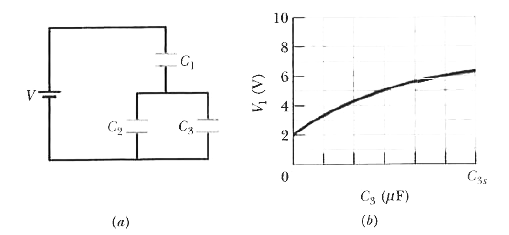
  6. Capacitor 3 in Fig. 25-40a is a variable capacitor (its capacitance C3...

    Text Solution

    |

  7. Figure 25-41 shows a circuit section of four air filled capacitors tha...

    Text Solution

    |

  8. A charged isolated metal sphere of diameter 15cm has a potential of 65...

    Text Solution

    |

  9. Two parallel plates of area 100 cm^2 are given charges of equal magnit...

    Text Solution

    |

  10. What is the capacitance of a drop that results when two mercury sphere...

    Text Solution

    |

  11. Plot 1 in fig25-42a gives the charge q that can be stored on capacitor...

    Text Solution

    |

  12. Figure 25-43 shows a 24.0 V battery and four uncharged capacitors of c...

    Text Solution

    |

  13. How many 12.5 mu F capacitors must be connected in parallel to store a...

    Text Solution

    |

  14. The space between two concentric conducting spherical shells of radii ...

    Text Solution

    |

  15. You have two flat metal plates, each of area 1.00 m^2 with which to co...

    Text Solution

    |

  16. The two metals objects in Fig 25-44 have net charges of +70pC and -70p...

    Text Solution

    |

  17. In fig.25-45 V=12V C1=10 mu F and C2=C3=20 mu F Switch S in first thro...

    Text Solution

    |

  18. A 100pF capacitor is charged to a potential difference of 80.0V and th...

    Text Solution

    |

  19. The plates of a spherical capacitor havi radii 37.0mm and 40.00 mm (a)...

    Text Solution

    |

  20. In fig.25-46 two parallel plate capacitors (with air between the plate...

    Text Solution

    |