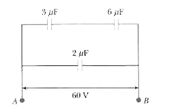
In the circuit shown in the following the potential difference across the `3 mu F` capacitor is
Text Solution
Verified by Experts
The correct Answer is:
D
Topper's Solved these Questions
CAPACITANCE
RESNICK AND HALLIDAY|Exercise PRACTICE QUESTION MATRIX MATCH|8 Videos
ALL ABOUT ATOMS
RESNICK AND HALLIDAY|Exercise CHECKPOINT|1 Videos
CENTER OF MASS
RESNICK AND HALLIDAY|Exercise Practice Questions (Integer )|4 Videos
Similar Questions
Explore conceptually related problems
In the circuit shown in the figure, the potential difference across the 4.5 muF capacitor is
In the circuit shown below: The potential difference across the 3 Omega resistor is:
In the circuit shown, the potential difference across the 3muF capacitor is V and the equivalent capacitance between A and B is C Then:
In the circuit shown in figure Find the potential differnece across capacitor.
In a ircuit shown in figure, the potential difference across the capacitor of 2muF is
In the circuit shown in the Figure, find the ratio of potential difference across capacitor 1 and 2. The capacitance values are as indicated in the Figure.
A capacitor of capacity 2muF is changed to a potential different of 12V . It is then connected across an inductor of inductance 0.6mH What is the current in the circuit at a time when the potential difference across the capacitor is 6.0V ?
A capacitor of capacity 2 muF is charged to a potential difference of 12 V . It is then connected across an inductor of inductance 6 mu H . What is the current (in A ) in the circuit at a time when the potential difference across the capacitor is 6.0 V ?
RESNICK AND HALLIDAY-CAPACITANCE-PRACTICE QUESTION (INTEGER TYPE)