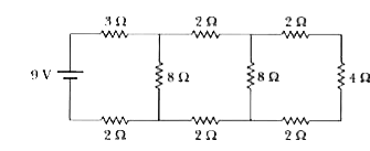
A
B
C
D
Text Solution
Verified by Experts
The correct Answer is:
Topper's Solved these Questions
CIRCUITS
RESNICK AND HALLIDAY|Exercise Practice Questions (More than One Correct Choice Type)|12 VideosCIRCUITS
RESNICK AND HALLIDAY|Exercise Practice Questions (Linked Comprehension)|11 VideosCIRCUITS
RESNICK AND HALLIDAY|Exercise Problems|45 VideosCENTER OF MASS
RESNICK AND HALLIDAY|Exercise Practice Questions (Integer )|4 VideosCIRCULAR MOTION
RESNICK AND HALLIDAY|Exercise CHECK POINTS|6 Videos
Similar Questions
Explore conceptually related problems
RESNICK AND HALLIDAY-CIRCUITS-Practice Questions (Single Correct Choice Type)
- In the circuit shown in the figure, the current through
Text Solution
|
- In the circuit shown P ne R the reading of galvonometer is same switch...
Text Solution
|
- In the given circuit, it is observed that the current I is independent...
Text Solution
|
- The three resistances of equal values are arranged in the different co...
Text Solution
|
- Given : R1 =1ohm, R2 = 2ohm, C1 = 2 muF, C2 = 4muF The time consta...
Text Solution
|
- Somewhere in a circuit is a resistor. A constant current is flowing in...
Text Solution
|
- If we go from A to B through the wire to the resistor, or choose a ran...
Text Solution
|
- 10C of charge start from the negative terminal of a battery, flow thro...
Text Solution
|
- A battery of emf E has an internal resistance r. A variable resistacne...
Text Solution
|
- The given gure shows a network of wiers carrying various currents. Wha...
Text Solution
|
- A current-carrying wire got pulled, stretching it and making it thinne...
Text Solution
|
- Four unequal resistors are connected in parallel. Which one of the fol...
Text Solution
|
- Three 100 W light bulbs are connected in series to a 220V power source...
Text Solution
|
- An ideal battery is connected to a circuit of four resistors as shown ...
Text Solution
|
- If voltage V is applied across terminals a and b of the circuit shown ...
Text Solution
|
- If the four light bulbs in the following figure are identical which ci...
Text Solution
|
- Which circuit diagram shows voltmeter V and ammeter A correctly positi...
Text Solution
|
- When a capacitor is discharged through a resistor, which of the follow...
Text Solution
|
- Two identical resistors of magnitude R and two identical capacitors of...
Text Solution
|
- A capacitor of capacity C is charged to a steady potential difference ...
Text Solution
|
