


Similar Questions
Explore conceptually related problems
Recommended Questions
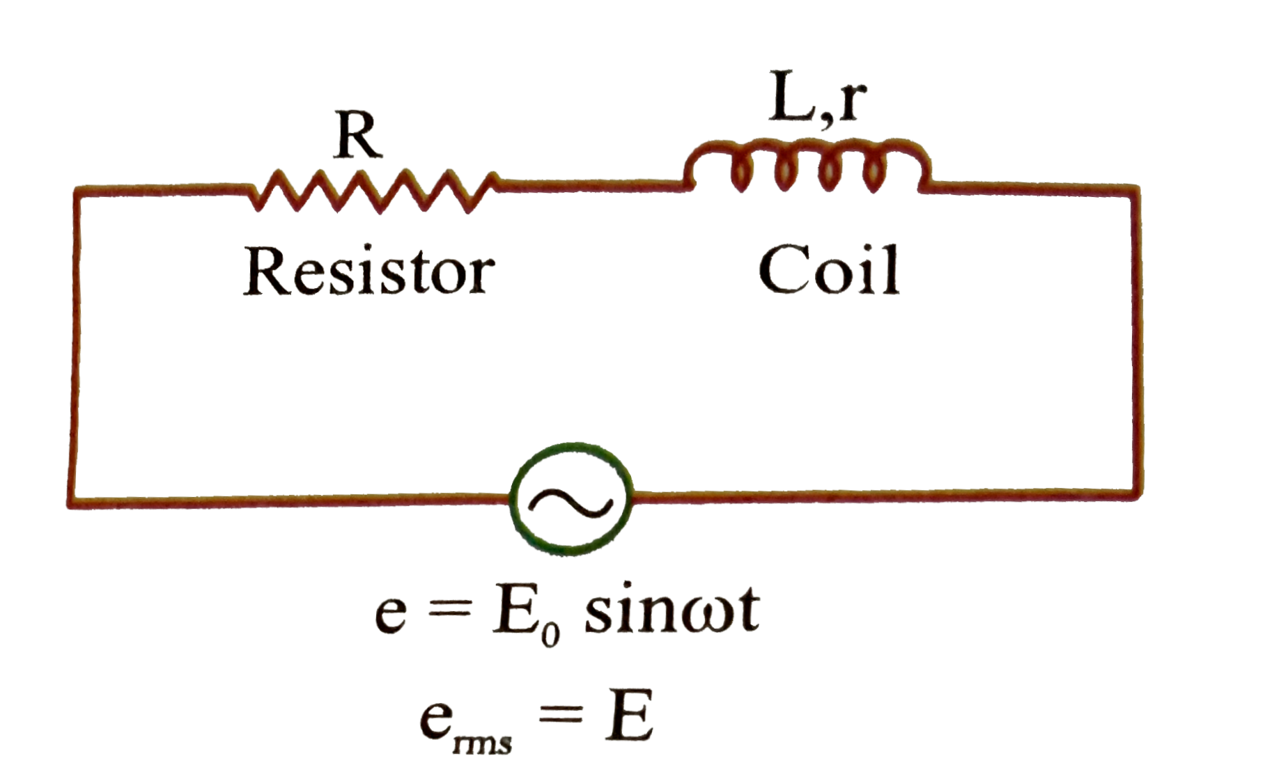
- For the circuit shown in the figure the rms value of voltage across R ...
Text Solution
|
- A 20volts AC is applied to a circuit consisting of a resistance and a...
Text Solution
|
- A series circuit consisting of an inductance - free resistance R=0.16 ...
Text Solution
|
- A series circuit consisting of an inductance free resistance R =0.16k ...
Text Solution
|
- For the circuit shown in the figure the rms value of voltage across R ...
Text Solution
|
- In the LCR circuit shown in figure (a) current will lead the voltage (...
Text Solution
|
- Maximum power developed across variable resistance R in the circuit sh...
Text Solution
|
- चित्र में दिखाये गये परिपथ में 4.5muF वाले संधारित्र पर विभवान्तर है
Text Solution
|
- In the circuit shown in figure, power developed across 1Omega,2Omegaan...
Text Solution
|