


Similar Questions
Explore conceptually related problems
Recommended Questions
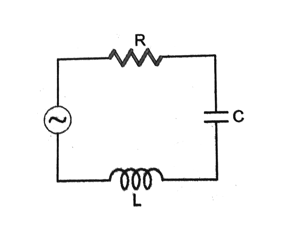
- Fig. show a series LCR circuit with L = 0.1 H , X(C ) = 14 Omega and R...
Text Solution
|
- A 9//100 (pi) inductor and a 12 Omega resistanace are connected in ser...
Text Solution
|
- A 0.21 H inductor and a 12 Omega resistance are connected in series to...
Text Solution
|
- A 0.21 H inductor and a 12 Omega resistance are connected in series t...
Text Solution
|
- Fig. show a series LCR circuit with L = 0.1 H l, X(C ) = 14 Omega and ...
Text Solution
|
- A 0.21-H inductor and a 88-Omega resistor are connected in series to a...
Text Solution
|
- किसी a.c. परिपथ में L=pi^(-1) H, R=300 Omega तथा स्रोत की आवृति 200 Hz...
Text Solution
|
- A 130 V 50 Hz AC supply is connected to a series combination of an ind...
Text Solution
|
- A series LCR circuit is connected top an AC power source of 220 V , 50...
Text Solution
|