Home
Class 12
PHYSICS
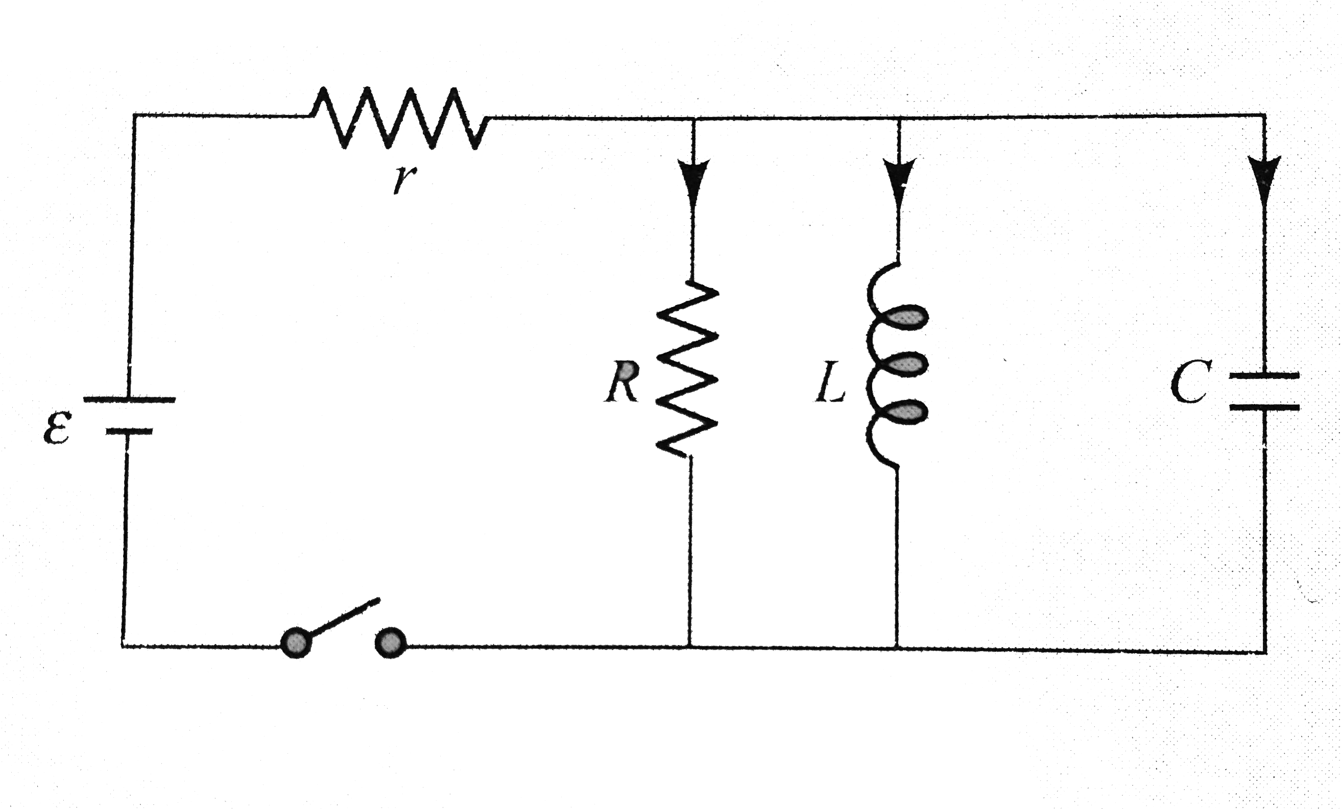
Figure shows an LCR circuit. When the sw...

Figure shows an `LCR` circuit. When the switch is closed, the currents through resistor `R`, inductor `L`, and capacitor `C` are `I_(1),I_(2)`, and `I_(3)`, respectively. Determine the values of `I_(1),I_(2)`, and `I_(3)`.

a. at `t = 0` b. at `t = oo`

Promotional Banner

Similar Questions

Explore conceptually related problems

Figure shows an L-R circuit. When the switch S is closed, the current through resistor R_(1), R_(2) and l_(3) are l_(1), l_(2) and l_(3) respectively. The value of l_(1), l_(2) and l_(3) at t=0 s is

In the circuit shown, the switch is closed at t=0 , the currents I_1, I_2 and I_3 are

In the circuit shown, the switch is closed at t=0 , the currents I_1, I_2 and I_3 are

In the circuit shown, the value of currents I_(1), I_(2) and I_(3) are

In the circuit shown, the value of currents I_(1), I_(2) and I_(3) are

Find the value of i (Current) at t=0 switch is closed, if initially current through inductors is zero,

Find the current I_(1) ,I_(2) and I_(3) through the there resistor circuit

In an L-R-C circuit the current is given by i = I cos omega t . The voltage amplitudes for the resistor. Inductor and capacitor are V_(R ), V_(L) and V_(C ) respectively. (a) The instantaneous power into the resistor is P_(R ) = V_(R ) I cos^(2) omega t . (b) The instantaneous into the inductor is P_(L) = - V_(L) I sin omega t cos omega t (c ) The instantaneous power into the capacitor is P_(c ) = V_(c ) I sin omega t cos omega t . (d) p_(R ) + p_(L) + P_(c ) equals total power p supplied by the source at each instant of time.

Find currents I_(1),I_(2) and I_(3) and the energy stored in the capacitors C_(1) and C_(2) in the circuit shown in figure.