Text Solution
Verified by Experts


Topper's Solved these Questions
XII BOARDS
XII BOARDS PREVIOUS YEAR|Exercise PHYSICS (Theory) DELHI BOARD -2016 [SET -I][COMPTT.]|12 VideosXII BOARDS
XII BOARDS PREVIOUS YEAR|Exercise C.B.S.E.CLASS-XII PHYSICS (THEORY) [SET-I] (SECTION-A)|5 VideosXII BOARDS
XII BOARDS PREVIOUS YEAR|Exercise SECTION-B|65 VideosSAMPLE PAPER 2019
XII BOARDS PREVIOUS YEAR|Exercise SECTION D|6 Videos
Similar Questions
Explore conceptually related problems
XII BOARDS PREVIOUS YEAR-XII BOARDS-SECTION-C
- State the reason, why the photodiode is always operated under reverse ...
Text Solution
|
- Draw the circuit diagram of a common emitter transistor amplifier. Wri...
Text Solution
|
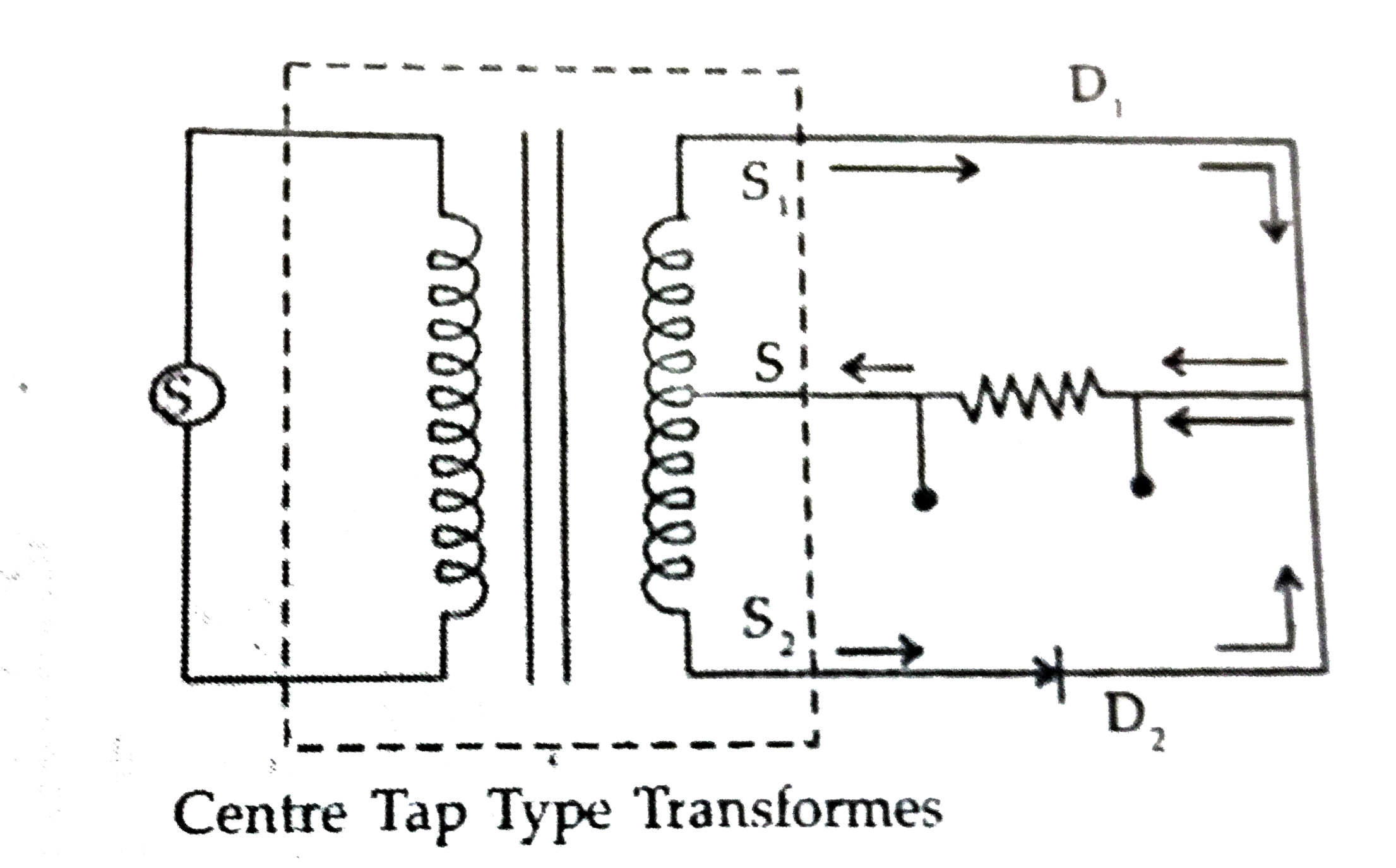
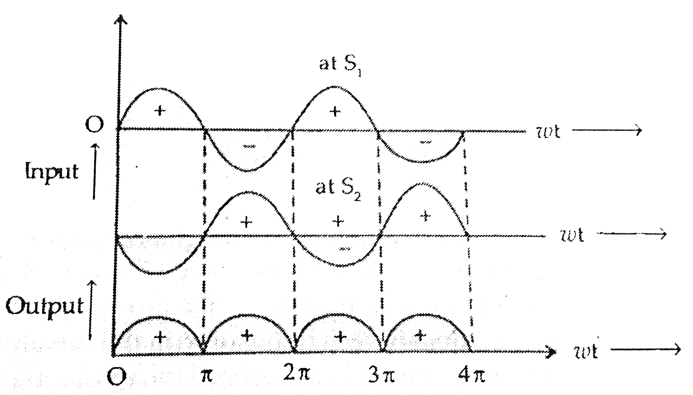
- Draw a circuit diagram of a full-wave rectifier. Explain its working p...
Text Solution
|
- Briefly explain the three factors which justify the need of modulating...
Text Solution
|
- The galvanometer, in each of the two given circuits deos not show any ...
Text Solution
|
- The current through two inductors of self inductance 12 mH and 30 mH i...
Text Solution
|
- (a) Explain how the intensity of diffraction pattern changes as the or...
Text Solution
|
- (a) Draw the equipotential surfaces corresponding to a uniform electri...
Text Solution
|
- Using Kirchoff's rules, calculate the current through the 40Omega" and...
Text Solution
|
- What is end error in a metre bridge ? How is it overcome ? The resist...
Text Solution
|
- (a) Identiy the part of the electromagnatic spectrum used in (i) radar...
Text Solution
|
- Define the term wavefront. Using Huygen's wave theory, verigy the law ...
Text Solution
|
- Define term, "refreactive index " of a medium. Verify Snell's law refr...
Text Solution
|
- (a) Dfine mutaul indutace and write its S.I. unit. (b) A square loop...
Text Solution
|
- (a) Derive the expression for the torque acting on a current carrying ...
Text Solution
|
- (i) A giant refracting telescope at an observatory has an objective le...
Text Solution
|
- (a) State Gauss's law for magnetism. Explain its significance. (b) ...
Text Solution
|
- Write three points of differences between para, dia-and ferro- mangeti...
Text Solution
|
- Define the term 'decay constant' of a radioactive sample. The of disin...
Text Solution
|
- Three photodiodes D1 , D2 and D3 are made of semiconductors having ...
Text Solution
|