 .
.


Similar Questions
Explore conceptually related problems
Recommended Questions
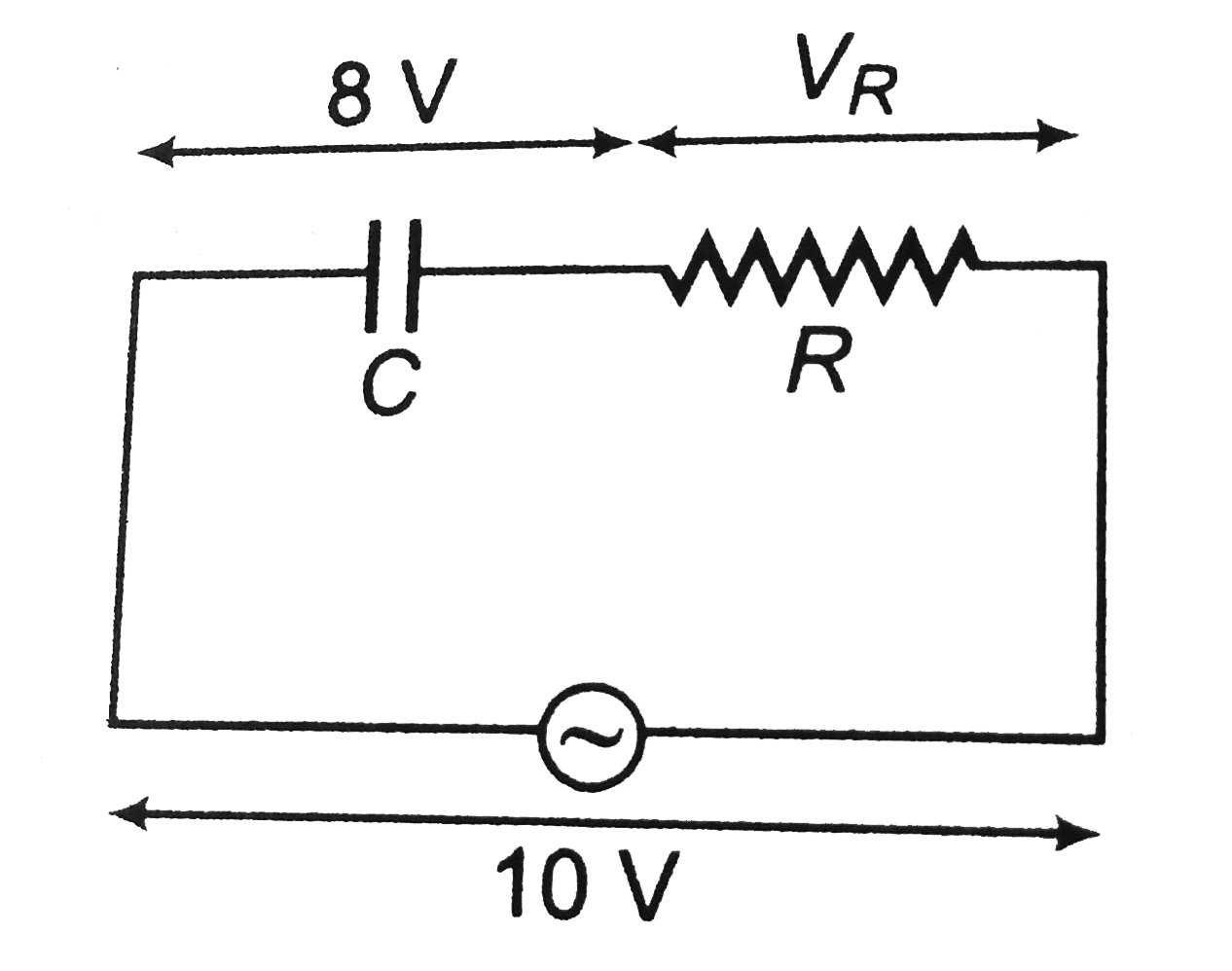
- In a series C-R circuit shown in figureure, the applied voltage is 10 ...
Text Solution
|
- A 50 Hz AC source of 20 V is connected across R and C as shown in figu...
Text Solution
|
- In a series C-R circuit shown in figureure, the applied voltage is 10 ...
Text Solution
|
- In a series LCR circuit, the voltages across an inductor, a capacitor ...
Text Solution
|
- In an LCR series circuit the voltages across R,L and C at resonance ar...
Text Solution
|
- In a series LCR circuit the voltage across an inductor, capacitor and ...
Text Solution
|
- In a series LCR circuit, rms voltage across inductor and capacitor are...
Text Solution
|
- In a series LCR circuit the voltage across an inductor, capacitor and ...
Text Solution
|
- In a series LCR circuit, the voltage across an inductor, a capacitor a...
Text Solution
|