


Similar Questions
Explore conceptually related problems
Recommended Questions
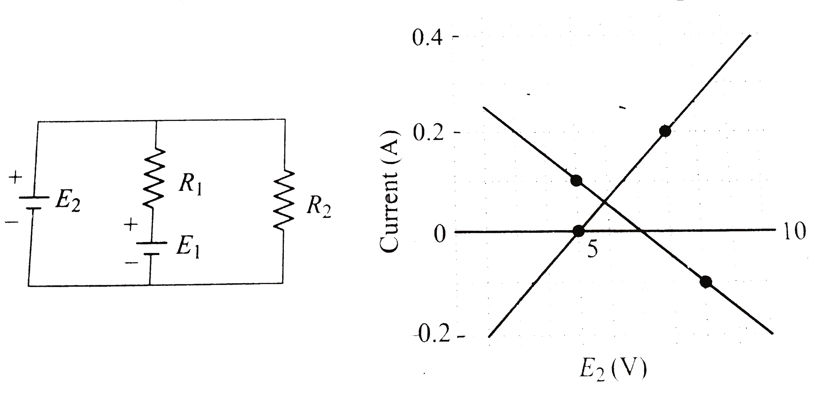
- In the circuit given in the figure, both batteries are ideal . Emf E1 ...
Text Solution
|
- In the circuit shown in fig. 5.265, E1 = E2 = E3 = 2V and R1 = R2 = 4O...
Text Solution
|
- Under what condition, the current passing through the resistance R can...
Text Solution
|
- In the circuit shown in Fig, the battery E1 has an emf of 12 V and zer...
Text Solution
|
- shows a circuit used in an experiment to determine the emf and interna...
Text Solution
|
- What should be the value of E1//E2 so that current flowing through 7 O...
Text Solution
|
- In the circuit given in the figure, both batteries are ideal . Emf E1 ...
Text Solution
|
- In the circuit given in the figure, both batteries are ideal . Emf E1 ...
Text Solution
|
- In the circuit givenn below, both batteries are ideal. EMF E(1) of bat...
Text Solution
|