


Similar Questions
Explore conceptually related problems
Recommended Questions
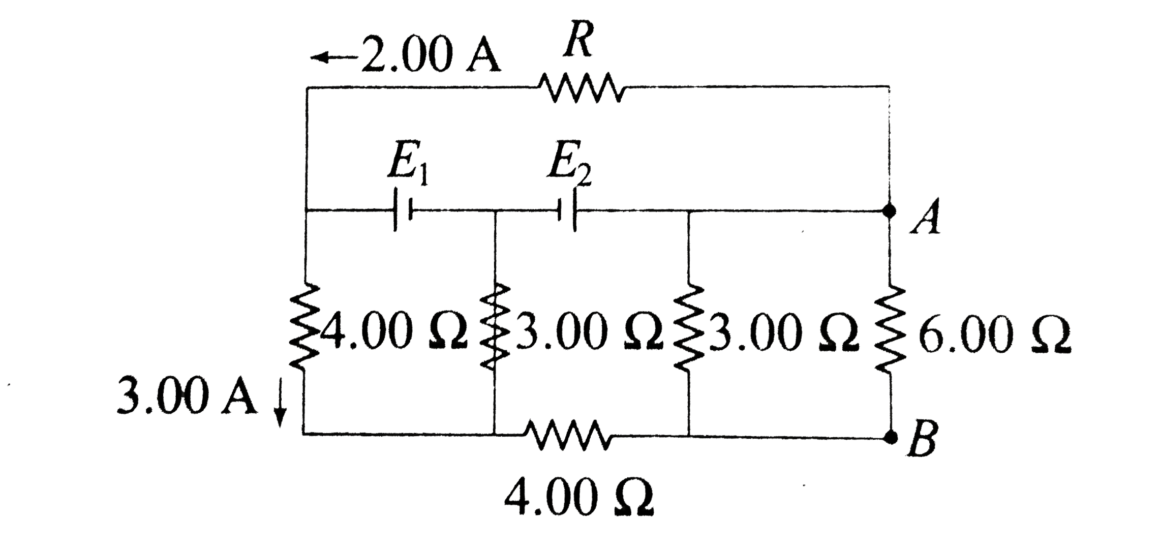
- In the circuit shown in figure, E1 and E2 are two ideal sources of unk...
Text Solution
|
- In the circuit shown in figure find: (a). the current in the 3.00 ...
Text Solution
|
- In the figure shown, at what distance (a) E2 will appear to E1 (b) E1 ...
Text Solution
|
- In the circuit shown in figure, E1 and E2 are two ideal sources of unk...
Text Solution
|
- A circuit shown in the figure consists of a battery of emf 10V and two...
Text Solution
|
- The current I, potential difference V(L) across the inductor and poten...
Text Solution
|
- In the circuit shown epsilon(1) and epsilon(2) are two ideal sources o...
Text Solution
|
- In the circuit shown in figure 3.154 find the potential difference V(A...
Text Solution
|
- Find current in 6Omega resistance and potential difference across each...
Text Solution
|