


Similar Questions
Explore conceptually related problems
Recommended Questions
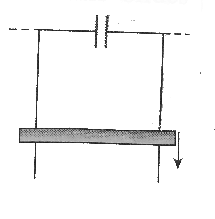
- Two vertical conducting rails separted by distance 1.0m are placed par...
Text Solution
|
- A conducting rod of length is moved at constant velocity v(0) on two p...
Text Solution
|
- A pair of parallel conducting rails lie at right angle to a uniform ma...
Text Solution
|
- Two vertical conducting rails separted by distance 1.0m are placed par...
Text Solution
|
- Figure shows a wire sliding on two parallel, conducting rails placed a...
Text Solution
|
- A pair of long, smooth, parallel, horizontal, conducting rails are joi...
Text Solution
|
- A wire having mass m and length 1 can freely slide on a pair or parall...
Text Solution
|
- There is a pair of fixed, parallel rails of negligible resistance in a...
Text Solution
|
- एक कॉपर की छड़ का द्रव्यमान m है। यह दो क्षैतिज समान्तर चिकनी पटरियों ...
Text Solution
|