


Similar Questions
Explore conceptually related problems
Recommended Questions
- In the circuit shown in figure, the silicon and germanium diodes start...
Text Solution
|
- Ge and Si diodes conduct at 0.3 V and 0.7 V respectively. In the follo...
Text Solution
|
- Calculate the value of output voltage V(0) (in V) if the Si diode and ...
Text Solution
|
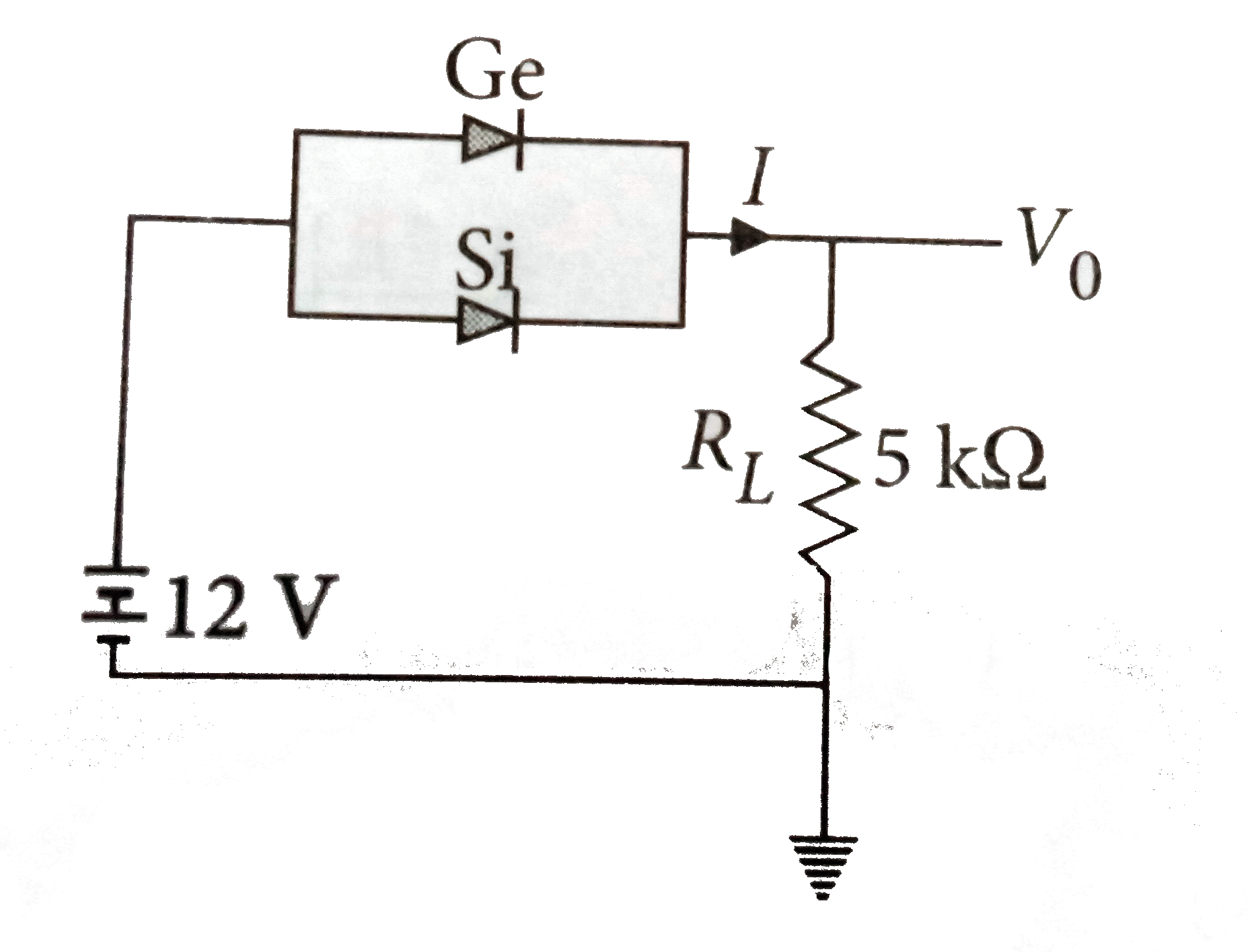
- Two junction diodes, one of germanium (Ge) and other of silicon (Si) a...
Text Solution
|
- Calculate the value of output voltageV(0) and I if the Si diode and th...
Text Solution
|
- The resistance of a germanium junction diode whose V-I is shown in fig...
Text Solution
|
- The diode D shown in the circuit is governed by the V-I relation V=(0....
Text Solution
|
- In the circuit shown in figure, the silicon and germanium diodes start...
Text Solution
|
- सिलिकॉन डायोड के निम्न प्रेक्षणों से डायोड प्रतिरोध की गणना कीजिए V ...
Text Solution
|