


Similar Questions
Explore conceptually related problems
Recommended Questions
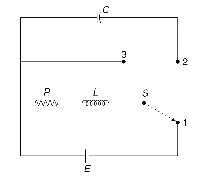
- In the circuit arrangement shown in Figure, the three way switch S is ...
Text Solution
|
- Determine the current through the battery in the circuit shown in figu...
Text Solution
|
- In the circuit shown in the figure, the switch S is in position 1 for ...
Text Solution
|
- In the circuit shown in fig, switch S was closed for long time. At tim...
Text Solution
|
- In the circuit shown, initially the switch is in position 1 for a long...
Text Solution
|
- In the circuit shown below, the switch is in position 1 for a long tim...
Text Solution
|
- In the circuit arrangement shown in Figure, the three way switch S is ...
Text Solution
|
- In the circuit shown in Figure, switch S(1) is kept closed and S(2) op...
Text Solution
|
- Consider the circuit shown in the figure. The switch has been in posit...
Text Solution
|