Text Solution
Verified by Experts


Topper's Solved these Questions
SEMICONDUCTOR ELECTRONICS : MATERIALS, DEVICES AND SIMPLE CIRCUITS
KUMAR PRAKASHAN|Exercise Section-C: NCERT Exemplar Solution (Multiple Choice Qustion (MCQs) )|8 VideosSEMICONDUCTOR ELECTRONICS : MATERIALS, DEVICES AND SIMPLE CIRCUITS
KUMAR PRAKASHAN|Exercise Section-C: NCERT Exemplar Solution (Multiple Choice Qustion (More than One Options))|8 VideosSEMICONDUCTOR ELECTRONICS : MATERIALS, DEVICES AND SIMPLE CIRCUITS
KUMAR PRAKASHAN|Exercise Section-B : Numericals (Numerical From Textual Exercise)|15 VideosSAMPLE QUESTION PAPER
KUMAR PRAKASHAN|Exercise PART-B SECTION-C|5 VideosWAVE OPTICS
KUMAR PRAKASHAN|Exercise SECTION-D (MULTIPLCE CHOICE QUESTIONS (MCQS)) (MCQS FROM DARPAN BASED ON TEXTBOOK)|239 Videos
Similar Questions
Explore conceptually related problems
KUMAR PRAKASHAN-SEMICONDUCTOR ELECTRONICS : MATERIALS, DEVICES AND SIMPLE CIRCUITS -Section-B : Numericals (Numerical From .DARPAN. Based On Textbook)
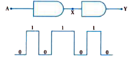
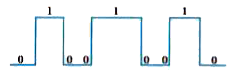
- A logic circuit is shown in the diagram. Draw the output signal at the...
Text Solution
|
- Prepare the truth table for the logic circuit given below.
Text Solution
|
- Which gate will be obtained by joining the two inputs of the NAND gate...
Text Solution
|
- Show that the circuit drawn in the figure comprising of 3 NAND gate be...
Text Solution
|
- Give truth table for a circuit shown in figure.
Text Solution
|
- A NAND gate of two input has an output is taken as input of NOT gate. ...
Text Solution
|
- A circuit of logic gte made from two AND gate is shown in following fi...
Text Solution
|
- The number density of electron is a semiconductor is 8xx10^(13) cm^(-3...
Text Solution
|
- What amount of inpurity of atomic density in added toform N-type semic...
Text Solution
|
- If an LED has to emit 662 nm wavelength of light then what should be ...
Text Solution
|
- The width of a depletion region is 400 nm. The intensity of the electr...
Text Solution
|
- For the circuit shown in the figure, calculate the equivalent resistan...
Text Solution
|
- Therefore are 6xx10^(19) electrons per unit cubic metre of pure semico...
Text Solution
|
- (A) Calculate the value of V(0) and i if the silicon and germanium dio...
Text Solution
|