A

B

C

D

Text Solution
Verified by Experts
The correct Answer is:


Topper's Solved these Questions
SEMICONDUCTOR ELECTRONICS : MATERIALS, DEVICES AND SIMPLE CIRCUITS
KUMAR PRAKASHAN|Exercise Section-C: NCERT Exemplar Solution (Multiple Choice Qustion (More than One Options))|8 VideosSEMICONDUCTOR ELECTRONICS : MATERIALS, DEVICES AND SIMPLE CIRCUITS
KUMAR PRAKASHAN|Exercise Section-C: NCERT Exemplar Solution (Very Short Answer Type Questions)|6 VideosSEMICONDUCTOR ELECTRONICS : MATERIALS, DEVICES AND SIMPLE CIRCUITS
KUMAR PRAKASHAN|Exercise Section-B : Numericals (Numerical From .DARPAN. Based On Textbook)|14 VideosSAMPLE QUESTION PAPER
KUMAR PRAKASHAN|Exercise PART-B SECTION-C|5 VideosWAVE OPTICS
KUMAR PRAKASHAN|Exercise SECTION-D (MULTIPLCE CHOICE QUESTIONS (MCQS)) (MCQS FROM DARPAN BASED ON TEXTBOOK)|239 Videos
Similar Questions
Explore conceptually related problems
KUMAR PRAKASHAN-SEMICONDUCTOR ELECTRONICS : MATERIALS, DEVICES AND SIMPLE CIRCUITS -Section-C: NCERT Exemplar Solution (Multiple Choice Qustion (MCQs) )
- The conductivity of a semiconductor increases with increase in temper...
Text Solution
|
- In figure, V(o) is the potential barrier across a p-n junction, when n...
Text Solution
|
- In figure, assuming the diodes to be ideal,
Text Solution
|
- A 220 V A.C. supply is connected betweeen points A and B (See figure...
Text Solution
|
- Hole is
Text Solution
|
- The output of the given circuit in figure.
Text Solution
|
- In the circuit shown in figure, if the diode forward voltage drop is 0...
Text Solution
|
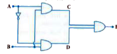
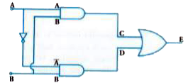
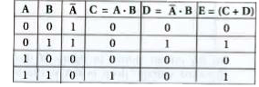
- Truth table for the given circuit (See figure) is
Text Solution
|