Text Solution
Verified by Experts


Topper's Solved these Questions
SEMICONDUCTOR ELECTRONICS : MATERIALS, DEVICES AND SIMPLE CIRCUITS
KUMAR PRAKASHAN|Exercise Section-D : Multiple Choice Questions (MCQs) (MCQs From .DARPAN. Based On Textbook)|116 VideosSEMICONDUCTOR ELECTRONICS : MATERIALS, DEVICES AND SIMPLE CIRCUITS
KUMAR PRAKASHAN|Exercise Section-D : Multiple Choice Questions (MCQs) (MCQs asked in Competitive Exams)|129 VideosSEMICONDUCTOR ELECTRONICS : MATERIALS, DEVICES AND SIMPLE CIRCUITS
KUMAR PRAKASHAN|Exercise Section-C: NCERT Exemplar Solution (Short Answer Type Questions)|8 VideosSAMPLE QUESTION PAPER
KUMAR PRAKASHAN|Exercise PART-B SECTION-C|5 VideosWAVE OPTICS
KUMAR PRAKASHAN|Exercise SECTION-D (MULTIPLCE CHOICE QUESTIONS (MCQS)) (MCQS FROM DARPAN BASED ON TEXTBOOK)|239 Videos
Similar Questions
Explore conceptually related problems
KUMAR PRAKASHAN-SEMICONDUCTOR ELECTRONICS : MATERIALS, DEVICES AND SIMPLE CIRCUITS -Section-C: NCERT Exemplar Solution (Long Answer Type Questions)
- If each diode in figure has a forward bias resistance of 25Omega and i...
Text Solution
|
- In the circuit shown in figure, when the input voltage of the base res...
Text Solution
|
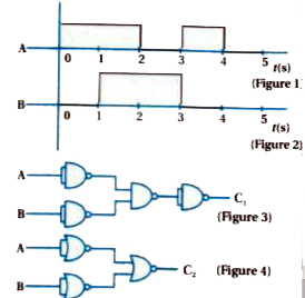
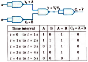
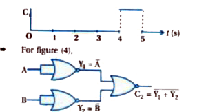
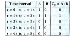
- Draw the output signals C(1) and C(2) in the given combination of gate...
Text Solution
|
- Consider the circuit arrangement shown in figure (1) for studying inpu...
Text Solution
|
- Assuming the ideal diode, draw the output waveform for the circuit giv...
Text Solution
|
- Suppose a 'n'-type wafer is created by dopin Si crystal having 5xx10^(...
Text Solution
|
- An X-OR gate has following truth table: It is represented by foll...
Text Solution
|
- Consider a box with three terminals on top of it as shown in figure (a...
Text Solution
|
- In the circuit shown in figure, when the input voltage of the base res...
Text Solution
|
- The output of the given circuit in figure.
Text Solution
|