A

B

C

D

Text Solution
Verified by Experts
The correct Answer is:


Topper's Solved these Questions
SEMICONDUCTOR ELECTRONICS : MATERIALS, DEVICES AND SIMPLE CIRCUITS
KUMAR PRAKASHAN|Exercise Section-D : Multiple Choice Questions (MCQs) (MCQs From .DARPAN. Based On Textbook)|116 VideosSAMPLE QUESTION PAPER
KUMAR PRAKASHAN|Exercise PART-B SECTION-C|5 VideosWAVE OPTICS
KUMAR PRAKASHAN|Exercise SECTION-D (MULTIPLCE CHOICE QUESTIONS (MCQS)) (MCQS FROM DARPAN BASED ON TEXTBOOK)|239 Videos
Similar Questions
Explore conceptually related problems
KUMAR PRAKASHAN-SEMICONDUCTOR ELECTRONICS : MATERIALS, DEVICES AND SIMPLE CIRCUITS -Section-D : Multiple Choice Questions (MCQs) (MCQs asked in Competitive Exams)
- A logic circuit is shown in the diagram. Draw the output signal at the...
Text Solution
|
- Carbon, silicon and germanium have four valence electrons each. At roo...
Text Solution
|
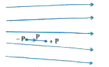
- Figure shows electric field lines in which an electric dipole P is pla...
Text Solution
|
- As shown in the following figure, take A and B input waveforms. Sketch...
Text Solution
|
- Which logic gate is represented by the following logic gates?
Text Solution
|
- If the output of the OR gate is connected to both inputs of the NAND g...
Text Solution
|
- Write the truth table for a NAND gate connected as given in figure. ...
Text Solution
|
- Why is I to V characteristic of a solar cell draw in the fourth quadra...
Text Solution
|
- Which of the following is correct
Text Solution
|
- If A and B are invertible matrices, then which of the following is not...
Text Solution
|
- Below is a list of plant fibres. From which part of the plant these ar...
Text Solution
|
- For common emitter configuration, if alpha and beta have their usual m...
Text Solution
|
- If X is the number of tails in three tosses of a coin, determine the s...
Text Solution
|
- In a common emitter amplifier circuit using a n-p-n transistor, the ph...
Text Solution
|
- The output of the given circuit in figure.
Text Solution
|
- In the circuit shown in figure, if the diode forward voltage drop is 0...
Text Solution
|
- Which of the following is true ?
Text Solution
|
- What is the difference between a nucleotide and nucleoside ? Give two ...
Text Solution
|
- Derive an expression for current I passing through an AC circuit conta...
Text Solution
|
- The depletion layer in the p-n junction region is caused by ……
Text Solution
|