A
B
C
D
Text Solution
Verified by Experts
The correct Answer is:


Topper's Solved these Questions
SEMICONDUCTOR ELECTRONICS : MATERIALS, DEVICES AND SIMPLE CIRCUITS
KUMAR PRAKASHAN|Exercise Section-D : Multiple Choice Questions (MCQs) (MCQs From .DARPAN. Based On Textbook)|116 VideosSAMPLE QUESTION PAPER
KUMAR PRAKASHAN|Exercise PART-B SECTION-C|5 VideosWAVE OPTICS
KUMAR PRAKASHAN|Exercise SECTION-D (MULTIPLCE CHOICE QUESTIONS (MCQS)) (MCQS FROM DARPAN BASED ON TEXTBOOK)|239 Videos
Similar Questions
Explore conceptually related problems
KUMAR PRAKASHAN-SEMICONDUCTOR ELECTRONICS : MATERIALS, DEVICES AND SIMPLE CIRCUITS -Section-D : Multiple Choice Questions (MCQs) (MCQs asked in Competitive Exams)
- If X is the number of tails in three tosses of a coin, determine the s...
Text Solution
|
- In a common emitter amplifier circuit using a n-p-n transistor, the ph...
Text Solution
|
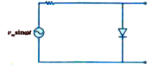
- The output of the given circuit in figure.
Text Solution
|
- In the circuit shown in figure, if the diode forward voltage drop is 0...
Text Solution
|
- Which of the following is true ?
Text Solution
|
- What is the difference between a nucleotide and nucleoside ? Give two ...
Text Solution
|
- Derive an expression for current I passing through an AC circuit conta...
Text Solution
|
- The depletion layer in the p-n junction region is caused by ……
Text Solution
|
- When a p-n junction diode is reverse biased, the flow of current acros...
Text Solution
|
- The output of OR gate is 1 ……..
Text Solution
|
- Barrier potential of a p-n junction diode does note depend on …….
Text Solution
|
- Which gate will be obtained by joining the two inputs of the NAND gate...
Text Solution
|
- Reverse bias applied to a junction diode ……
Text Solution
|
- In semiconductor at a room temperature ………
Text Solution
|
- The peak voltage in the output of a half wave diode rectifier fed wit...
Text Solution
|
- The output of OR gate is 1 ……..
Text Solution
|
- Choose the only false statement from the following.
Text Solution
|
- Application of a forward bias to a p-n junction ………
Text Solution
|
- Zener diode use for ….
Text Solution
|
- An AND gate is followed by a NOT gate in series with two inputs A and ...
Text Solution
|