A
B
C
D
Text Solution
Verified by Experts
The correct Answer is:


Topper's Solved these Questions
SEMICONDUCTOR ELECTRONICS : MATERIALS, DEVICES AND SIMPLE CIRCUITS
KUMAR PRAKASHAN|Exercise Section-D : Multiple Choice Questions (MCQs) (MCQs From .DARPAN. Based On Textbook)|116 VideosSAMPLE QUESTION PAPER
KUMAR PRAKASHAN|Exercise PART-B SECTION-C|5 VideosWAVE OPTICS
KUMAR PRAKASHAN|Exercise SECTION-D (MULTIPLCE CHOICE QUESTIONS (MCQS)) (MCQS FROM DARPAN BASED ON TEXTBOOK)|239 Videos
Similar Questions
Explore conceptually related problems
KUMAR PRAKASHAN-SEMICONDUCTOR ELECTRONICS : MATERIALS, DEVICES AND SIMPLE CIRCUITS -Section-D : Multiple Choice Questions (MCQs) (MCQs asked in Competitive Exams)
- When the inputs of a two input logic gate are 0 and 0, the output is 1...
Text Solution
|
- Justify the output waveform (Y) of the OR gate for the following input...
Text Solution
|
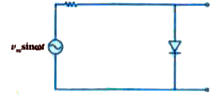
- The output of the given circuit in figure.
Text Solution
|
- In a n-type semiconductor, which of the following statement is true?
Text Solution
|
- The potential barrier of the p-n junction depends …….. (i) On kind o...
Text Solution
|
- In a n-type semiconductor, which of the following statement is true?
Text Solution
|
- A helicopter is moving in upward direction with speed of 10 m/s. If th...
Text Solution
|
- Which logic gate is represented by the following logic gates?
Text Solution
|
- A cell of emf E and internal resistance r is connected across an exter...
Text Solution
|
- Derive an expression for current I passing through an AC circuit conta...
Text Solution
|
- In the circuit shown the reading of voltmeter V(3) and Ammeter 'A' wil...
Text Solution
|
- Justify the output waveform (Y) of the OR gate for the following input...
Text Solution
|
- If A and B are two matrices of the order 3xxmand3xxn , respectively , ...
Text Solution
|
- Which of the following logic gate is an universal gate?
Text Solution
|
- In the circuit shown in figure, when the input voltage of the base res...
Text Solution
|
- In a p-n junction diode, change in the temperature due to heating …….
Text Solution
|
- Which of the following can be used as a biocontrol agent in the treatm...
Text Solution
|
- For a p-type semiconductor, which of the following statements is true?
Text Solution
|
- Obtain the resonant frequency and Q-factor of a series LCR circuit wit...
Text Solution
|
- A circular loop enters a uniform magnetic field as shown in the figure...
Text Solution
|