Text Solution
Verified by Experts
The correct Answer is:


Topper's Solved these Questions
ALTERNATING CURRENT
NCERT EXEMPLAR ENGLISH|Exercise Short Answer types questions|1 VideosALTERNATING CURRENT
NCERT EXEMPLAR ENGLISH|Exercise Long Answe types Questions|5 VideosALTERNATING CURRENT
NCERT EXEMPLAR ENGLISH|Exercise Long Answe types Questions|5 VideosATOMS
NCERT EXEMPLAR ENGLISH|Exercise Long Answer Type|6 Videos
Similar Questions
Explore conceptually related problems
NCERT EXEMPLAR ENGLISH-ALTERNATING CURRENT-Very short Answer types questions
- If a LC circuit is considered analogous to a harmonically osicallting ...
Text Solution
|
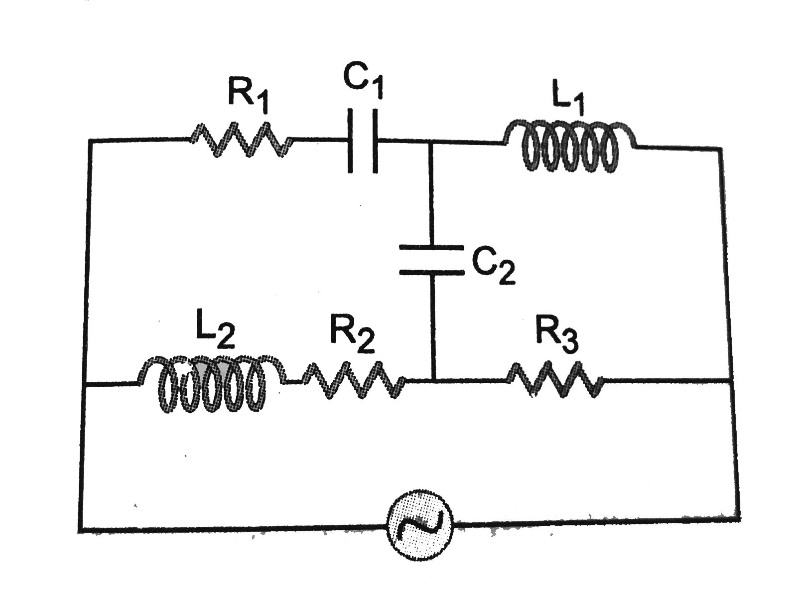
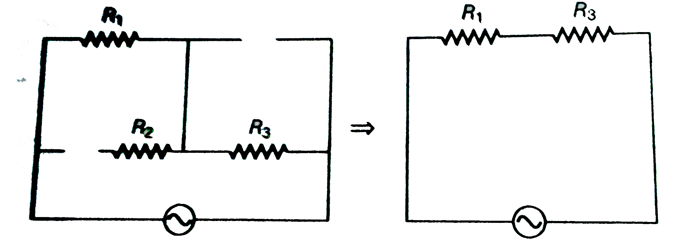
- Draw the effective equivalent circuit of the circuit show in Fig. at v...
Text Solution
|
- Study the circuit (a) and (b) shown in Fig. and answer the following q...
Text Solution
|
- Can the instantaneous power output of an ac source ever be negative ? ...
Text Solution
|
- In series LCR circuit, the plot of I("max") versus omega is shown in f...
Text Solution
|
- The alternating current in a circuit is described by the graph shown i...
Text Solution
|
- How does the sign of the phase angle phi, by which the supply voltage ...
Text Solution
|
- Both alternating current and direct are measured in ampers. But how is...
Text Solution
|
- A coil of 0.01 henry inductance and 1 ohm resistance is connected to 2...
Text Solution
|
- A 60 W load is connected to the secondary of a transformer whose prima...
Text Solution
|
- Explain why the reactance provided by a capacitor to an alternating cu...
Text Solution
|
- Explain why the reactance offered by an inductor increases with increa...
Text Solution
|