Text Solution
Verified by Experts


Topper's Solved these Questions
Similar Questions
Explore conceptually related problems
NCERT EXEMPLAR ENGLISH-NUCLEI-Long answer type question
- If each diode in figure has a forward bias resistance of 25 Omega and ...
Text Solution
|
- In the circuit shown in Fig. when the input voltage of the base resist...
Text Solution
|
- Draw the output signals C(1) " and " C(2) in the given combination of ...
Text Solution
|
- Consider the circuit arrangnent shown in Fig. for studying input and o...
Text Solution
|
- Assuming the ideal diode, draw the output waveform for the circuit giv...
Text Solution
|
- Suppose a 'n'- type wafer is created by doping Si crystal having 5xx10...
Text Solution
|
- An X-OR gate has following truth table: It is represented by followi...
Text Solution
|
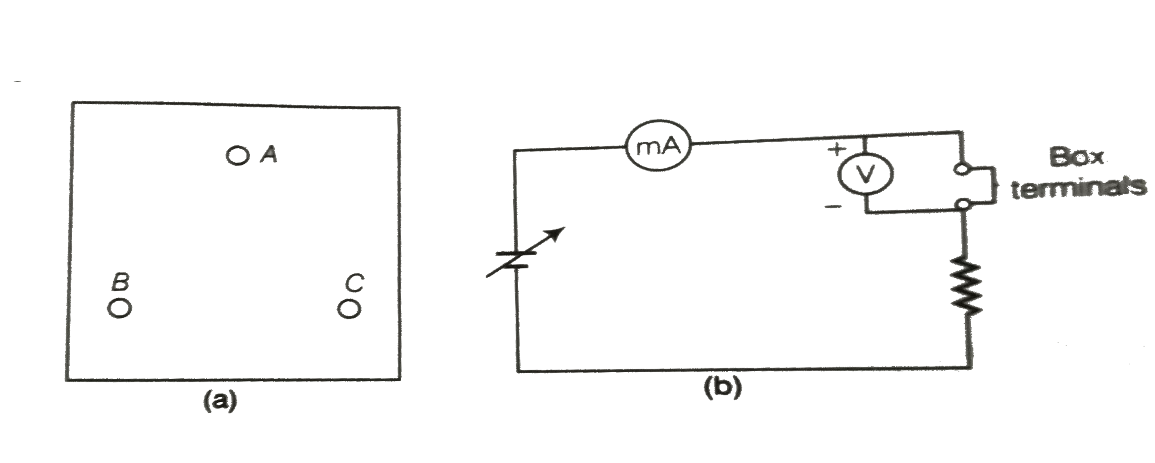
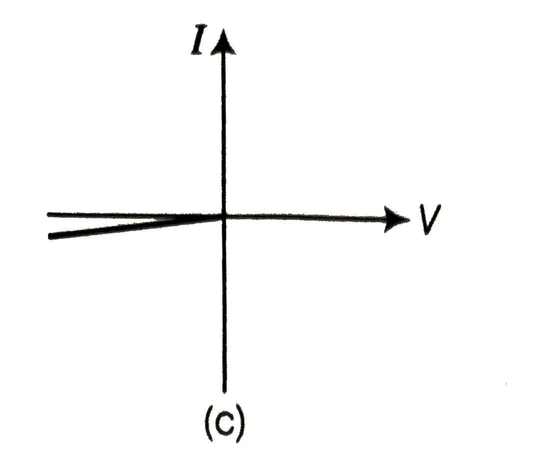
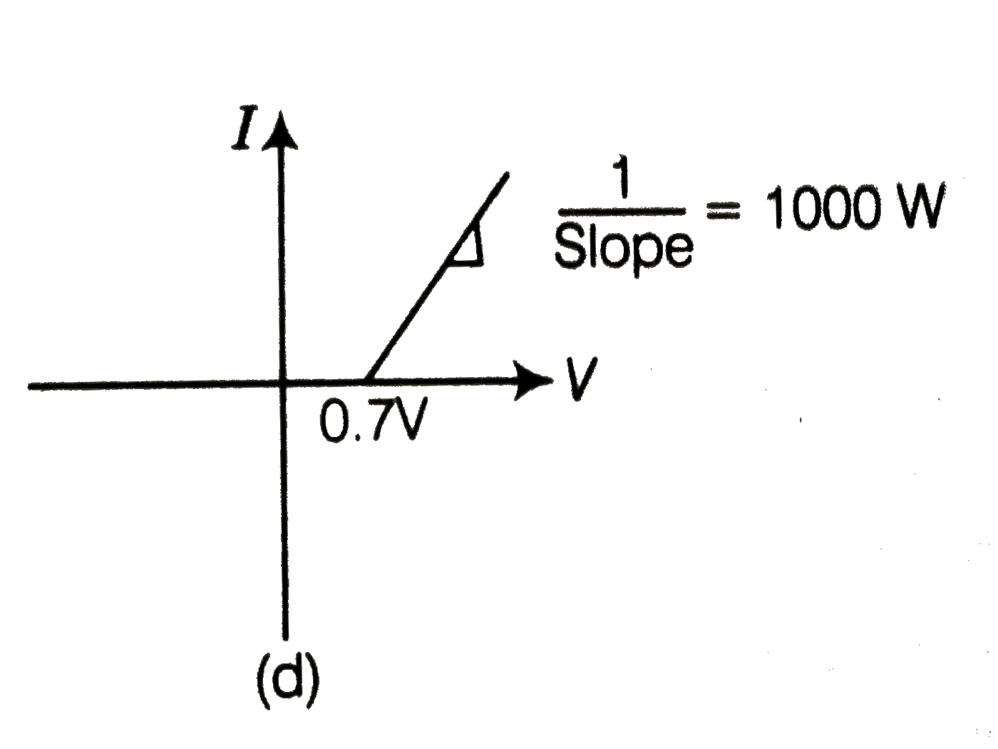
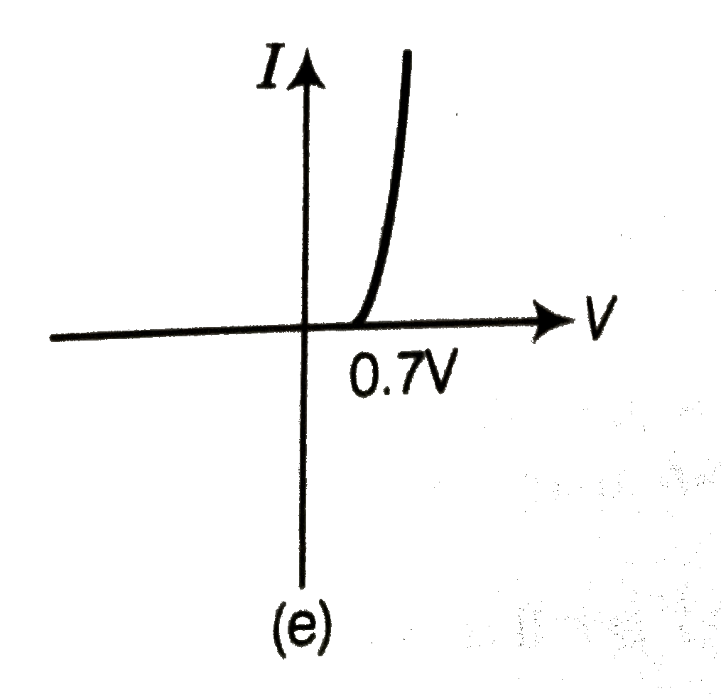
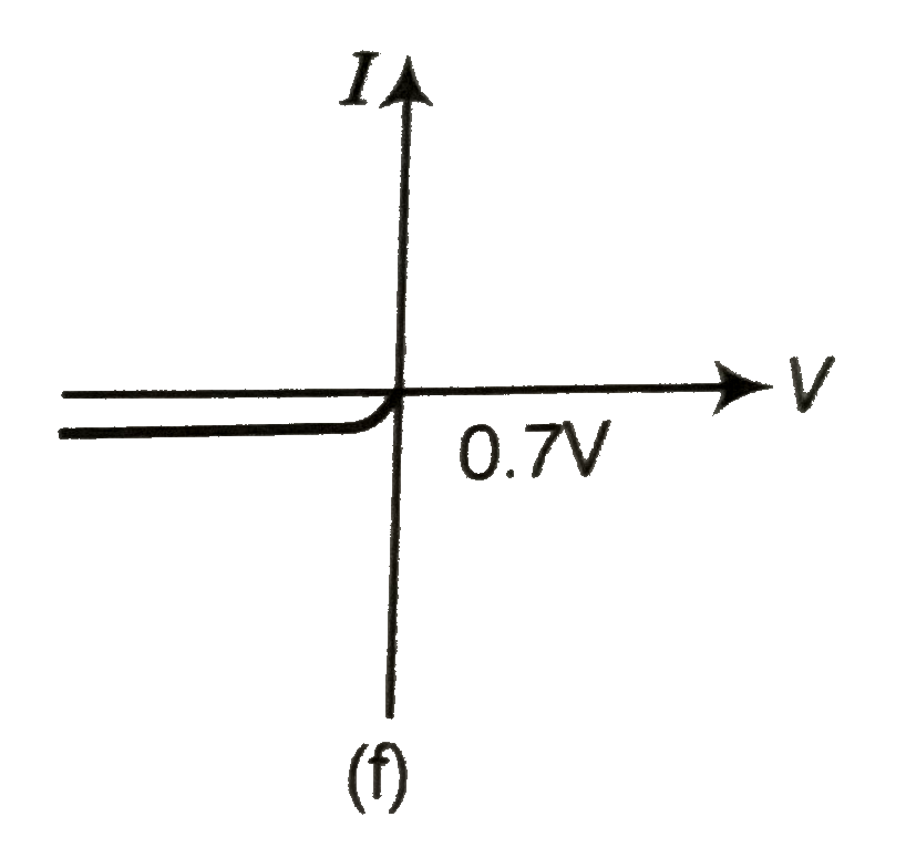
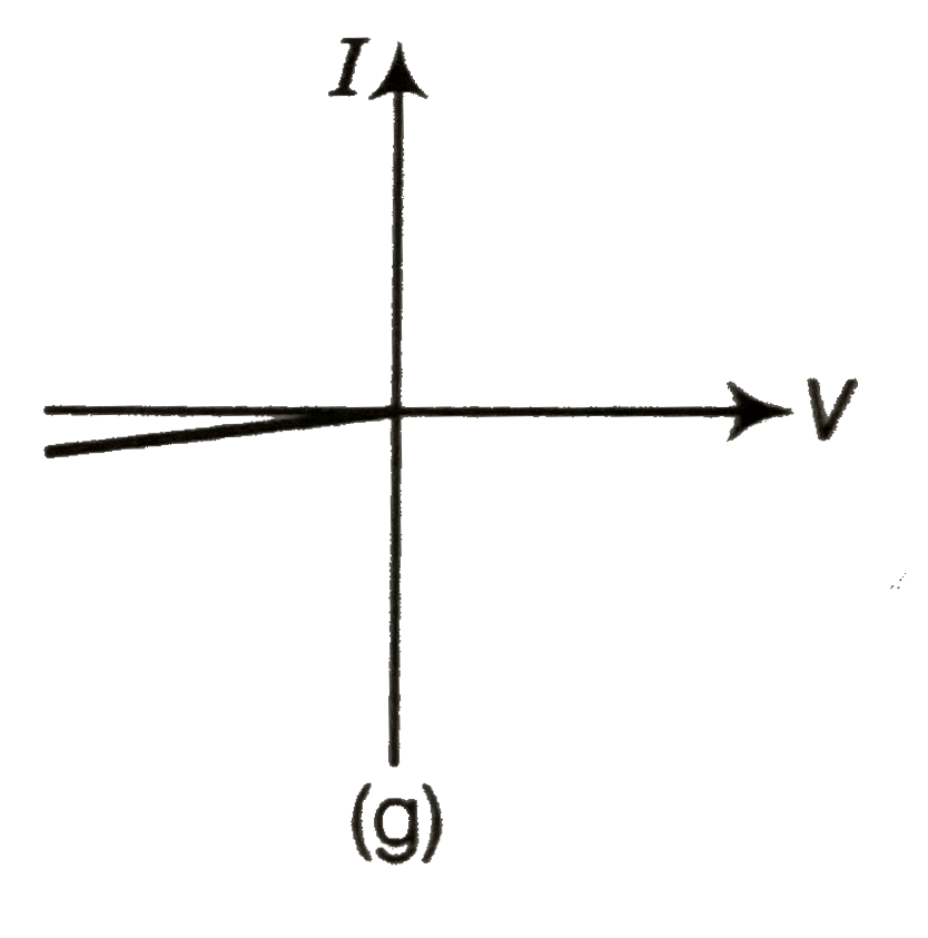
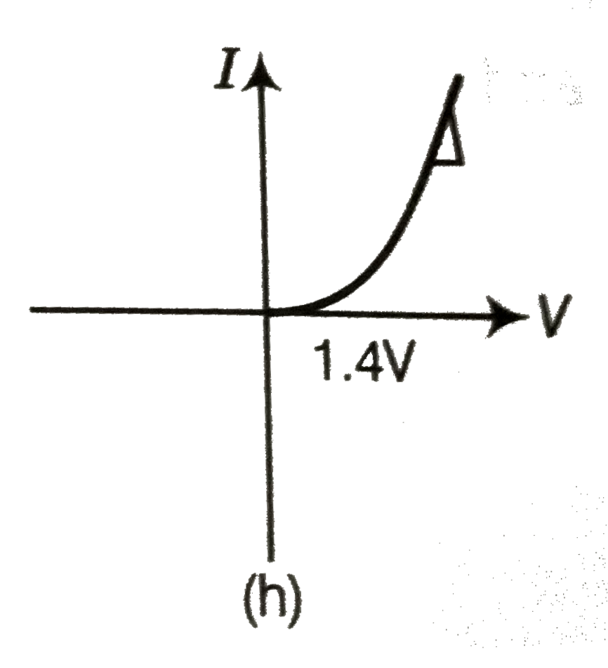
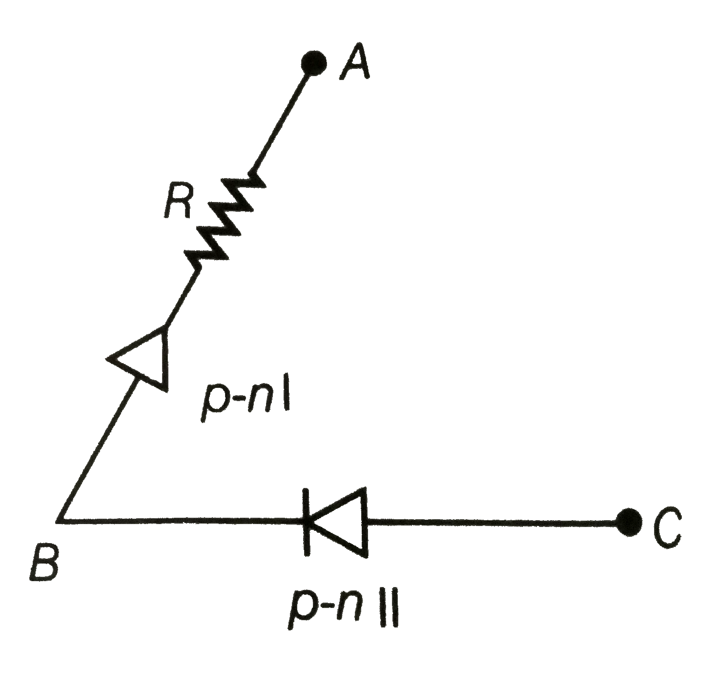
- Consider a box with three terminals on top of it as shown in figure. ...
Text Solution
|
- For the transistor circuit shown in figure , evaluate VE , RB and RE. ...
Text Solution
|
- In the circuit shown in fig. (a), final the value of R(C).
Text Solution
|