Text Solution
Verified by Experts


Topper's Solved these Questions
Similar Questions
Explore conceptually related problems
NCERT EXEMPLAR ENGLISH-ELECTROMAGNETIC INDUCTION -Long
- A magnetic field B = B(0) sin (omega t) hat k covers a large region wh...
Text Solution
|
- A conducting wire XY of mass M and negligible resistance slides smothl...
Text Solution
|
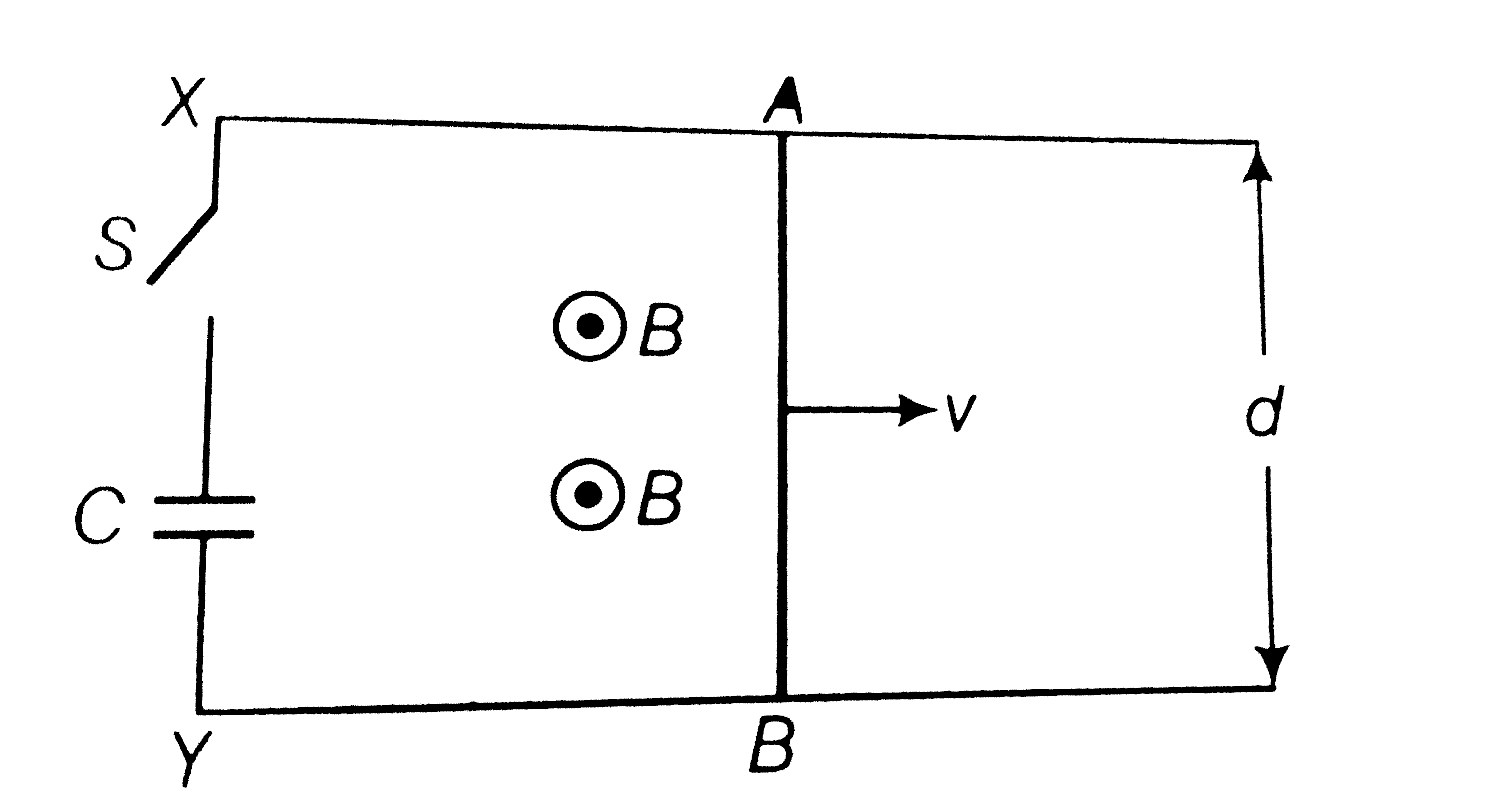
- ODBAC is a fixed rectangular conductor of negligible resistance (C0 is...
Text Solution
|
- Consider an infinitely long wire carrying a current I (t), With (dI)...
Text Solution
|
- A rectangular loop of wire ABCD is kept close to an infinitely long wi...
Text Solution
|
- A magnetic field B is confined to a region r le a and points out of th...
Text Solution
|
- A rod of mass m and resistance R slides smoothly over two parallel per...
Text Solution
|
- Find the current in the sliding rod AB (resistance = R) for the arrang...
Text Solution
|
- Find the current in the sliding rod AB (resistance = R) for the arrang...
Text Solution
|
- A metallic ring of field. If z is the radius l (ring being horizontal ...
Text Solution
|
- A long solenoid 'S' has 'n' turns per meter, with diameter 'a'. At the...
Text Solution
|