Home
Class 12
PHYSICS
The emf (epsilon)and the internal resist...

The emf `(epsilon)`and the internal resistance r of the battery shown in figure are 4.3V and `1.0 Ohm` respectively.The external resistance R is `50 ohm`.The resistances of the ammeter and voltmeter are `2.0 ohm and `200ohm respectively.(a)Find the reading of the two meters.(b) The switch is thrown to the other side, What will be the readings of the two meters now?

Text Solution

Verified by Experts

(a) In circuit ABFGA,
` i_1 50 + 2i + i-4.3= 0 `
` rArr 50 i_1 + 3i = 4.3 ` ……….(i) `
` In circuit BEDCB, `
` rArr 50i_1-(i-i_1)xx 200 = 0 `
` rArr 50i_1 -200i +200i_1 = 0 `
` rArr 250 i_1 = 200i `
` rArr 50i_1 - 40i = 0 ` .........(ii)
` Solving equation (i) and (ii) we get `
`43i = 4.3 `
` rArr i = 0.1 `
` rArr 5i_1 = 4 xx i = 4 xx 0.1 `
` i_1 = 0.4/5 A. `
The current read by Ammeter, i = 0.1A
Voltameter reads a pot. diff.
` = i_1 xx 50 = 4V`
(b) In circuit ABEFA,
` 50i_1 + 2i_1 + 1i - 4.3= 0 `
` rArr 52i_1 + i - 4.3 = 0 `
` rArr 200(52i_1 + i - 4.3) = 0 `
` In circuit BCDEB, `
` (i-i_1)200 -2i-50i_1= 0 `
` rArr 200i -252i_1 = 0 `
` (10400+252) i_1 = 4.3 xx 2 xx 100 `
` rArr i_1(10652) = 4.3 xx 2 xx 100`
` rArr i=((4.3 xx 2 xx 100) /10652) = 0.08 `
` i = 4.3 - 52 xx 0.08 = 0.14. `
Reading of the ammeter = 0.08A
Reading of the voltameter
= (0.14 - 0.08)200
= 12 V .
Promotional Banner

Topper's Solved these Questions

  • ELECTRIC CURRENT IN CONDUCTORS

    HC VERMA ENGLISH|Exercise questions for short answer|17 Videos
  • ELECTRIC CURRENT IN CONDUCTORS

    HC VERMA ENGLISH|Exercise objective 2|9 Videos
  • DISPERSION AND SPECTRA

    HC VERMA ENGLISH|Exercise Question for short Answer|6 Videos
  • ELECTRIC CURRENT THROUGH GASES

    HC VERMA ENGLISH|Exercise Short answer|6 Videos

Similar Questions

Explore conceptually related problems

The emf E and the internal resistance r of the battery shown in figure are 4.3V and 1.0Omega respectively. The external resistan ce R is 50Omega . The resistance of the ammeter and voltameter are 2.0Omega an d 200Omega respectively. Find the respective reading of the voltmeter.

In the circuit shown the reading of ammeter and voltmeter are 4 A and 20 V respectively. The meters are non ideal, then R ia

Resistance in the two gaps of a meter bridge are 10 ohm and 30 ohm respectively. If the resistances are interchanged he balance point shifts by

In the adjoining circuit diagram, the readings of ammeter and voltmeter are 2 A and 120 V, respectively. If the value of R is 75Omega , then the voltmeter resistance will be

The resistance of the four arms P, Q, R and S in a Wheatstone's bridge are 10 ohm 30 ohm and 90 ohm rerspectively. The e.m.f. and internal resistance of the cell are 7 V and 5 ohm respectively. If the galvanometer resistance is 50 ohm , the current drawn for the cell will be

In the adjoining circuit, the e.m.f. of the cell is 2 volt and the internal resistance is negligible. The resistance of the voltmeter is 80 ohm . The reading of the voltmeter will be

The diagram in Fig. shows a cell of e.m.f. epsi = 2 volt and internal resistance r = 1 ohm connected to an external resistance R = 4 ohm. The ammeter A measures the current in the circuit and the voltmeter V measures the terminal voltage across the cell. What will be the readings of the ammeter and voltmeter when the key K is open

The diagram in Fig. shows a cell of e.m.f. epsi = 2 volt and internal resistance r = 1 ohm connected to an external resistance R = 4 ohm. The ammeter A measures the current in the circuit and the voltmeter V measures the terminal voltage across the cell. What will be the readings of the ammeter and voltmeter when the key K is closed.

A battery of emf epsilon and internal resistance r is connected across a load resistance R_L . The plot between output power and load resistance is shown in the figure. The value of emf epsilon and internal resistance r respectively will

A cell of e.m.f. 2V and negligible internal resistance is connected to resistor R_(1) and R_(2) as shown in the figure. The resistance of the Voltmeter R_(1) and R_(2) are 80Omega,40Omega and 80Omega respectively. The reading of the voltmeter is:-

HC VERMA ENGLISH-ELECTRIC CURRENT IN CONDUCTORS-Exercises
  1. Find the equivalent resistances of the network shown in figure between...

    Text Solution

    |

  2. An infinite ladder is constructed with 1(Omega)and 2(Omega)resistor as...

    Text Solution

    |

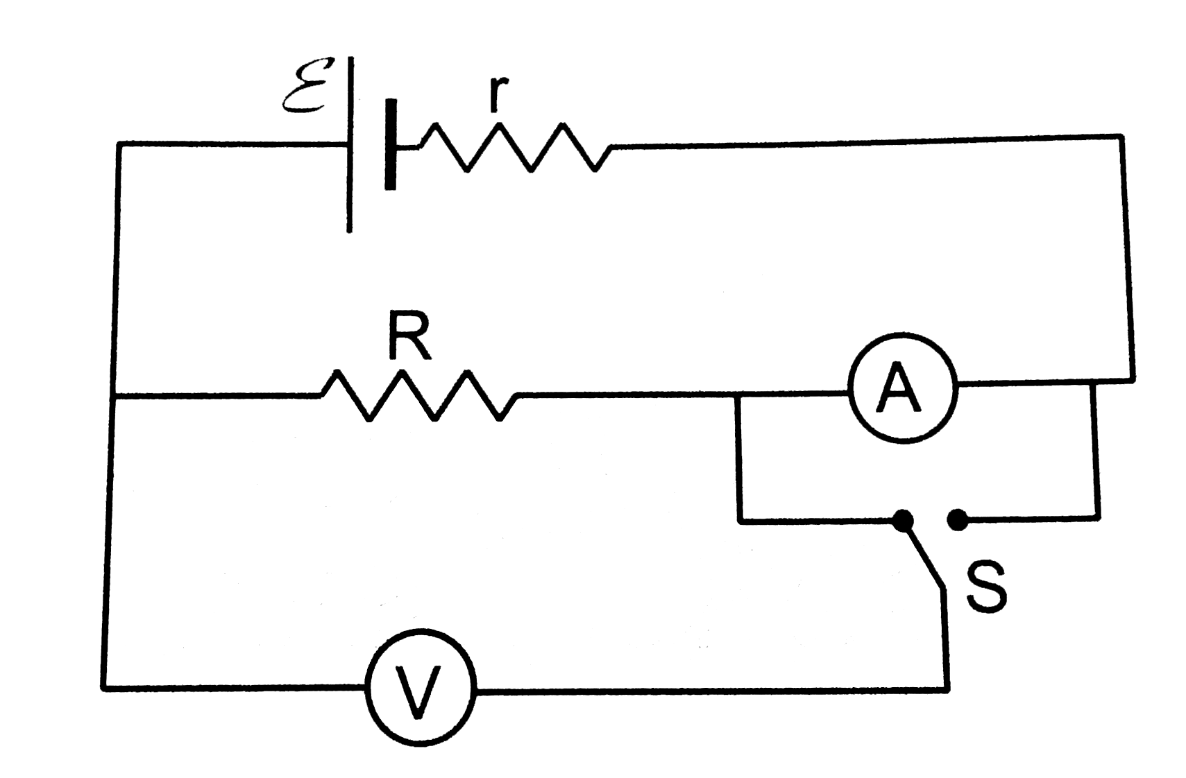
  3. The emf (epsilon)and the internal resistance r of the battery shown in...

    Text Solution

    |

  4. A voltmeter of resistances 400(Omega)is used to measure the potential ...

    Text Solution

    |

  5. The voltmeter shown in figure reads 18V across the 50(Omega)resistor. ...

    Text Solution

    |

  6. A voltmeter consists of a 25(Omega) coil connected in series with a 57...

    Text Solution

    |

  7. An ammeter is to be constructed which can read currents up to 2.0A. If...

    Text Solution

    |

  8. A voltmeter coil has resistance 50.0(Omega)and a resistor of 1.15k(Ome...

    Text Solution

    |

  9. The potentiometer wire AB shown in figure is 40 cm long. Where should ...

    Text Solution

    |

  10. The potentiometer wire AB shown in figure is 50cm long.When AD=30cm, n...

    Text Solution

    |

  11. A 6-volt battery of negligible internal resistance is connected across...

    Text Solution

    |

  12. Consider the potentiometer circuit arranged as in figure. The potentio...

    Text Solution

    |

  13. Find the charge on the capacitor shown in figure

    Text Solution

    |

  14. (a) Find the current in the 20(Omega)resistor shown in figure.(b)If a ...

    Text Solution

    |

  15. Find the charge on the four capacirtors of capacitances 1(mu)F,2(mu)F,...

    Text Solution

    |

  16. find the potential difference between th point A and B and between the...

    Text Solution

    |

  17. A capacitance C, a resistance R and an emf (epsilon)are connected in s...

    Text Solution

    |

  18. A parallel-plate capacitor with plate are 20cm^(2)and plate separation...

    Text Solution

    |

  19. A capacitor of capacitance 10(mu)F is connected to a battery of emf 2V...

    Text Solution

    |

  20. A 20(mu)Fcapacitor is joined to a battery of emf 6.0V through a resist...

    Text Solution

    |