Home
Class 12
PHYSICS
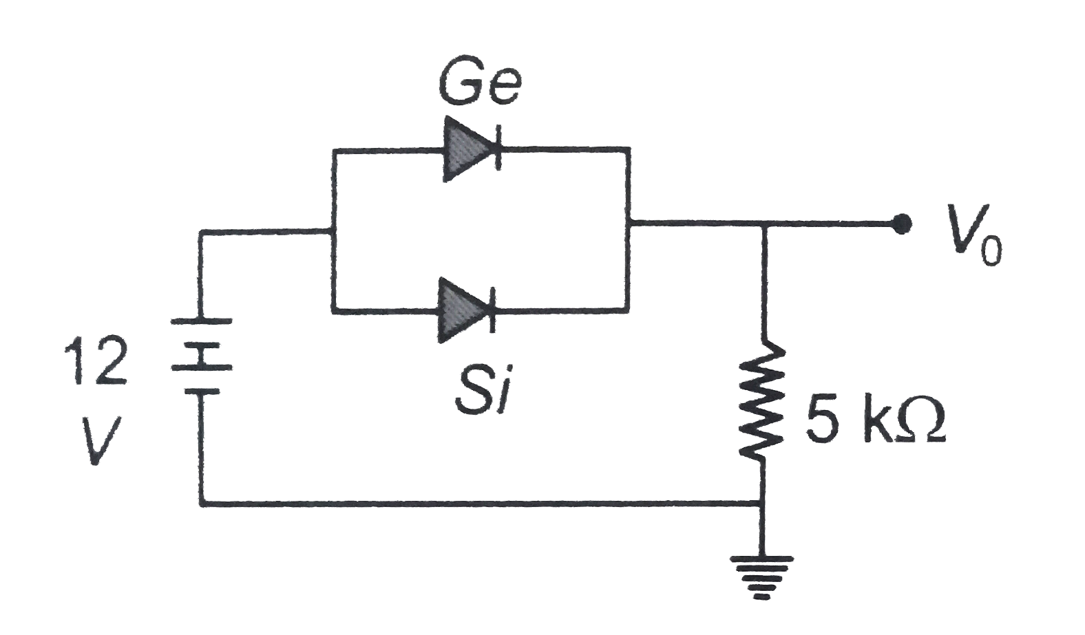
Ge and Si diodes conduct at 0.3 V and 0....

`Ge` and `Si` diodes conduct at `0.3 V` and `0.7 V` respectively. In the following figure if `Ge` diode connection are reversed, the value of `V_(0)` changes by

A

0.8 V

B

0.6 V

C

0.2 V

D

0.4 V

Text Solution

Verified by Experts

Promotional Banner

Similar Questions

Explore conceptually related problems

Calculate the value of V_(0) and I If the Si diode and the Ge diode start conducting ar 0.7 V and 0.3 volt respectively. In the given circuit. If the Ge diode connection be reversed. What will the new value of V_(0) and I ? .

In the circuit shown in figure, the silicon and germanium diodes start conducting at 0.7 V and 0.3 V respectively. What are the values of V_0 and I?

In the circuit shown in figure, if the diode forward voltage drop is 0.3 V, then the voltage difference between A to B is,

In the circuit shown in figure, if the A diode forward voltage drop is 0.3 V, the voltage difference between A and B is

The standard E_(red)^(@) Values if A, B and C are + 0.68V , - 0.76V , -0.50V respectively. The order of their reducing power is :

Two junction diodes, one of germanium (Ge) and other of silicon (Si) are connected as shown in fig to a battery of 12 V and a load resistance 10 kOmega . The germanium diode conducts at 0.3 V and silicon diode at 0.7 V . When current flows in the circuit, the potential of terminal Y will be .

The junction diode in the following circuit requires a minimum current of 1 mA to be above the knee point (0.7 V) of its I-V characterstic curve. The voltage across the diode is independent of current above the knee point. If V_(B)=5 V , then the maximum value of R so that the voltage is above the knee point, will be

Two cells of emfs 1.5 V and 2.0v having internal resistance 0.2 Sigma and 0.3 Sigma respectively are connected in parallel . Calculate the emf and internal resistance of the equivalent cell .

In the figure, D is an ideal diode and an alternating voltage of peak value 10 volts si connected as input V_(1) . Which of the following figures represents the correct waveform of output voltage V_(0) ?

When the reverse potential in a semiconductor diode are 10 V and 30 V, thent he corresponding reverse currents are 25muA . And 50muA respectively. The reverse resistance of junction diode will be-