Home
Class 12
PHYSICS
The circuit shown in the figure contains...

The circuit shown in the figure contains two diodes each with a forward resistance of 30 `Omega` and with infinite backward resistance. If the battery is 3 V, the current through the 50 `Omega` resistance (in ampere) is

A

Zero

B

0.01

C

0.02

D

0.03

Text Solution

Verified by Experts

The correct Answer is:
C

In the circuit, the upper diode `D_(1)` is reverse biased and the lower diode `D_(2)` is forward biased. Thus, there will be no current across upper diode junction. The effective circuit will be as shown in figure.

Total resistance of cricuit, `R=50+70+30=150Omega`
Current in circuit, `I=(V )/(R )=(3V)/(150Omega)=0.02A`
Promotional Banner

Topper's Solved these Questions

  • ELECTRONIC DEVICES

    MTG GUIDE|Exercise CHECK YOUR BEET VITALS|25 Videos
  • ELECTRONIC DEVICES

    MTG GUIDE|Exercise AIPMT/NEET (MCQs)|42 Videos
  • ELECTRONIC DEVICES

    MTG GUIDE|Exercise AIPMT/NEET (MCQs)|42 Videos
  • ELECTROMAGNETIC WAVES

    MTG GUIDE|Exercise AIPMT/NEET(MCQs)|15 Videos
  • ELECTROSTATICS

    MTG GUIDE|Exercise AIPMT/NEET (MCQ.s)|34 Videos

Similar Questions

Explore conceptually related problems

The circuit shown in the figure contains two diodes each with a forward resistance of 50 Omega and with infinite backward resistance. If the battery is 6 V, the current through the 100 Omega resistance (in ampere) is

The circuit shown in the figure contains three diodes each with forward resistance of 50 ohms and with infinite backward resistance. If the battery voltage is 6 V, the current through the 100 ohm resistance is

The circuit contains two diodes each with a forward resistance of 50Omega and with infinite reverse resistance. If the battery voltage is 6V, the current through the 120Omega resistance is_ mA

The circuit shown in figure (1) Contains two diodes each with a forward resistance of 50 ohm and with infinite reverse resistance. If the battery voltage is 6 V , the current through the 100 ohm resistance is. .

The circuit shown in following figure contanis two diode D_(1) and D_(2) each with a forward resistance of 50 ohm and with infinite backward resistance. If the battery voltage is 6V , the current through the 100 ohm resistance (in amperes) is

Two diodes D_(1) and D_(2) each with forward resistance of 50 omega and infinite backward resistance are connected as the current througjh thej 150 omega resistance is

The circuit showm below constains tow ideal diodes, each with a forward resistance of 50 Omega . If the battery voltage is 6 V, the current through the 100 Omega resistance ( in Amperes) is:

In the circuit, the current flowing through 10 Omega resistance

In the given circuit, the diode has a forward resistance of 8 Ω and infinite backward resistance. The value of R is :-

MTG GUIDE-ELECTRONIC DEVICES-NEET CAFÉ (TOPICWISE PRACTICE QUESTIONS)
  1. When p-n junction diode is forward biased then

    Text Solution

    |

  2. In an unbiased p-n junction, holes diffuse from the p-region to n-regi...

    Text Solution

    |

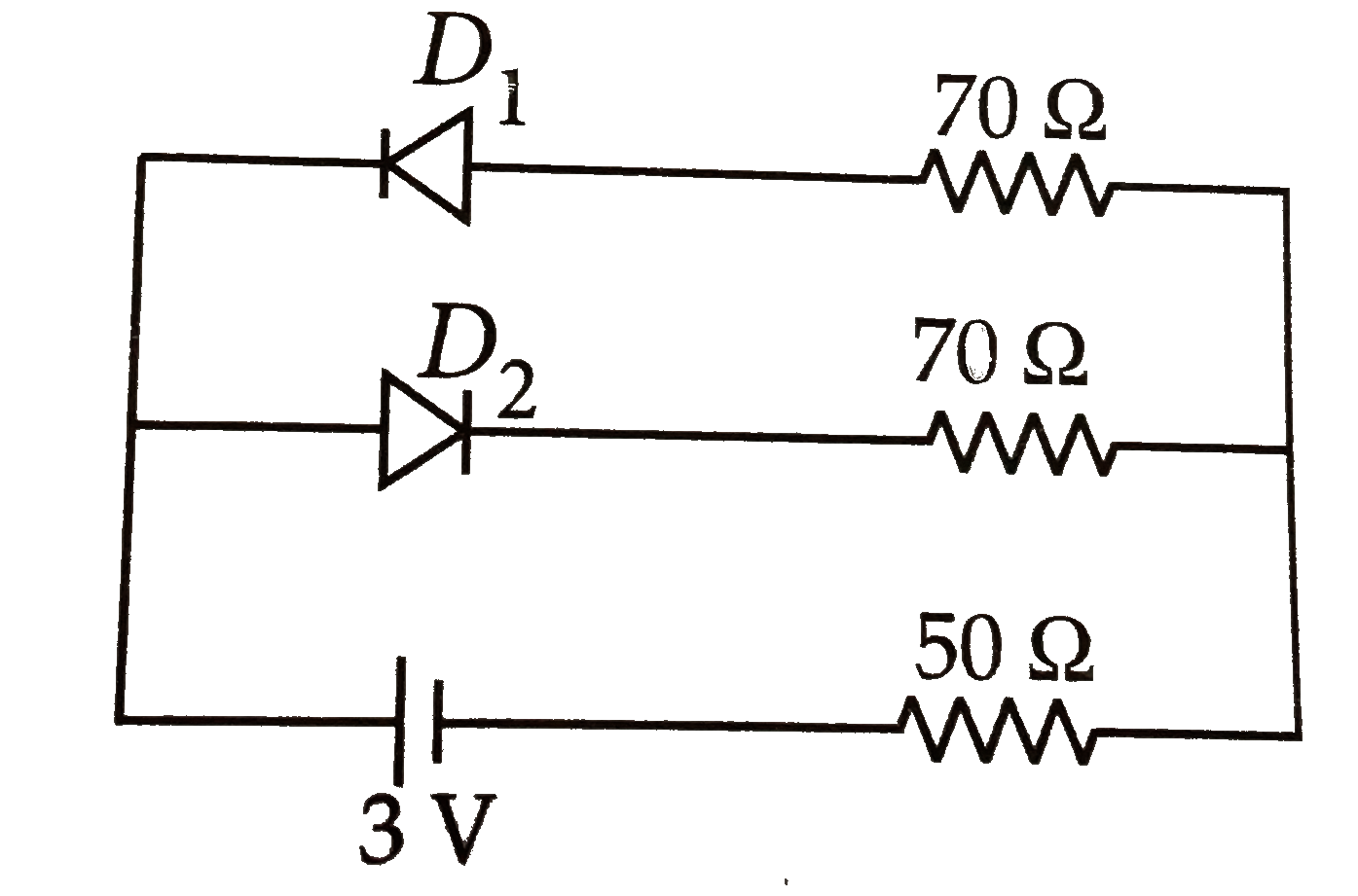
  3. The circuit shown in the figure contains two diodes each with a forwar...

    Text Solution

    |

  4. In the circuit shown, the reading of the ammeter if diode is not ideal...

    Text Solution

    |

  5. Current through the ideal diode as shown in figure is

    Text Solution

    |

  6. The dominant mechanisms for motion of charge carriers in forward and r...

    Text Solution

    |

  7. A junction diode has a resistance of 25 Omega when forward biased and...

    Text Solution

    |

  8. Two identical p-n junctions may be connected in series in which a batt...

    Text Solution

    |

  9. In the given circuit the current through the battery is

    Text Solution

    |

  10. In the given circuit for ideal diode, the current through the battery ...

    Text Solution

    |

  11. When the voltage drop across a p.n junction diode is increased from 0....

    Text Solution

    |

  12. In the diode circuit shown in figure,

    Text Solution

    |

  13. The current through the ideal diode as shown in the figure is

    Text Solution

    |

  14. In which of the following figures, junction diode is forward biased?

    Text Solution

    |

  15. The circuit shown in the figure contains three diodes each with forwar...

    Text Solution

    |

  16. The vallue of ripple factor for full wave rectifier is

    Text Solution

    |

  17. Which is the correct diagram of a half- wave reactifier?

    Text Solution

    |

  18. Which of the following circuits provides full wave rectification of an...

    Text Solution

    |

  19. With an ac input from 50 Hz power line, the ripple frequency is

    Text Solution

    |

  20. In a half wave rectifier circuit operating from 50 Hz mains frequency,...

    Text Solution

    |