Home
Class 12
PHYSICS
The circuit shown in the figure contains...

The circuit shown in the figure contains three diodes each with forward resistance of 50 ohms and with infinite backward resistance. If the battery voltage is 6 V, the current through the 100 ohm resistance is

A

0

B

36 mA

C

43 mA

D

50 mA

Text Solution

Verified by Experts

The correct Answer is:
B

In the given circuit, the upper two diodes `D_(1) and D_(2)` are forward biased and the lower diode `D_(3)` is reverse biased. Hence no diode `D_(3)` The equivalent circuit is as shwon in the figure.

As diode `D_(1)` and `150 Omega` resistor are in series and their combination is in parallel with the series combination of diode `D_(2) and 50Omega` resistor. Theri equivalent resistance is
`(1)/(R.)=(1)/(r_(f)+150Omega)+(1)/(r_(f)+50Omega)=(1)/(50Omega+150Omega)+(1)/(50Omega+50Omega)`
`(1)/(R.)=(1)/(200Omega)+(1)/(100Omega) rArr R.=(200)/(3)Omega`
Total resitance of the circuti, `R=100Omega+(200)/(3)Omega=(500)/(3)Omega`
Current in the circuit,
`I=(V)/(R )=(6V)/((500)/(3)Omega)=3.6xx10^(-2)A=36mA`
Promotional Banner

Topper's Solved these Questions

  • ELECTRONIC DEVICES

    MTG GUIDE|Exercise CHECK YOUR BEET VITALS|25 Videos
  • ELECTRONIC DEVICES

    MTG GUIDE|Exercise AIPMT/NEET (MCQs)|42 Videos
  • ELECTRONIC DEVICES

    MTG GUIDE|Exercise AIPMT/NEET (MCQs)|42 Videos
  • ELECTROMAGNETIC WAVES

    MTG GUIDE|Exercise AIPMT/NEET(MCQs)|15 Videos
  • ELECTROSTATICS

    MTG GUIDE|Exercise AIPMT/NEET (MCQ.s)|34 Videos

Similar Questions

Explore conceptually related problems

The circuit shown in figure (1) Contains two diodes each with a forward resistance of 50 ohm and with infinite reverse resistance. If the battery voltage is 6 V , the current through the 100 ohm resistance is. .

The circuit shown in the figure contains two diodes each with a forward resistance of 50 Omega and with infinite backward resistance. If the battery is 6 V, the current through the 100 Omega resistance (in ampere) is

The circuit shown in the figure contains two diodes each with a forward resistance of 30 Omega and with infinite backward resistance. If the battery is 3 V, the current through the 50 Omega resistance (in ampere) is

The circuit shown in following figure contanis two diode D_(1) and D_(2) each with a forward resistance of 50 ohm and with infinite backward resistance. If the battery voltage is 6V , the current through the 100 ohm resistance (in amperes) is

The circuit contains two diodes each with a forward resistance of 50Omega and with infinite reverse resistance. If the battery voltage is 6V, the current through the 120Omega resistance is_ mA

Find current through 4 ohm resistance

Two diodes D_(1) and D_(2) each with forward resistance of 50 omega and infinite backward resistance are connected as the current througjh thej 150 omega resistance is

The circuit showm below constains tow ideal diodes, each with a forward resistance of 50 Omega . If the battery voltage is 6 V, the current through the 100 Omega resistance ( in Amperes) is:

MTG GUIDE-ELECTRONIC DEVICES-NEET CAFÉ (TOPICWISE PRACTICE QUESTIONS)
  1. The current through the ideal diode as shown in the figure is

    Text Solution

    |

  2. In which of the following figures, junction diode is forward biased?

    Text Solution

    |

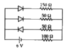
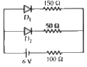
  3. The circuit shown in the figure contains three diodes each with forwar...

    Text Solution

    |

  4. The vallue of ripple factor for full wave rectifier is

    Text Solution

    |

  5. Which is the correct diagram of a half- wave reactifier?

    Text Solution

    |

  6. Which of the following circuits provides full wave rectification of an...

    Text Solution

    |

  7. With an ac input from 50 Hz power line, the ripple frequency is

    Text Solution

    |

  8. In a half wave rectifier circuit operating from 50 Hz mains frequency,...

    Text Solution

    |

  9. A Zener diode when used as a voltage regulator is connected (a) in f...

    Text Solution

    |

  10. A p - n photodiode is fabricated from a semiconductor with band gap of...

    Text Solution

    |

  11. Consider the following statements A and B and identify the correct ans...

    Text Solution

    |

  12. A Zener diode is specified as having a breakdown voltage of 9.1 V, wit...

    Text Solution

    |

  13. From the Zener diode circuit shown in figure, the current through the ...

    Text Solution

    |

  14. In the circuit given, the current through the Zener diode is

    Text Solution

    |

  15. If the voltage between the terminals A and B is 17 V and Zener brekdow...

    Text Solution

    |

  16. GaAs (with a band gap =1.5eV) as an LED can emit

    Text Solution

    |

  17. In the following circuit, the current flowing through 1kOmega. resisto...

    Text Solution

    |

  18. Identify the mismatch of the following.

    Text Solution

    |

  19. The device used for detecting optical signal is

    Text Solution

    |

  20. A zener diode has a contact potential of 1 V in the absence of biasi...

    Text Solution

    |